Compression ignition internal combustion engine

a technology of compression ignition and internal combustion engine, which is applied in the direction of machines/engines, electrical control, output power, etc., can solve the problems of narrow operation area of self-ignition and difficulty in stable driving of vehicles

Inactive Publication Date: 2006-08-15
HITACHI LTD
View PDF27 Cites 37 Cited by
  • Summary
  • Abstract
  • Description
  • Claims
  • Application Information

AI Technical Summary

Benefits of technology

[0010]Such a configuration makes compatible an increase in the compression self-ignition operating area with an optimum output torqu

Problems solved by technology

However, the internal combustion engine described in JP-A-11-280507 has the following problems.
That is, when the opening/closing timings required for the intake valve and exhaust valve vary depending on the engine operating condition, both timings cannot be controlled independently of each other, which causes a problem that the operating area by self-ignition is narrowed.
Furthermore, the conventional engine system that combines the self-ignitio

Method used


Image

  • Compression ignition internal combustion engine
  • Compression ignition internal combustion engine
  • Compression ignition internal combustion engine

Examples


first embodiment

[0050]With reference now to FIG. 1 to FIG. 14, a configuration and operation of a compression ignition internal combustion engine according to the present invention will be explained below.

[0051]First, a configuration of the compression ignition internal combustion engine according to the first embodiment will be explained by using FIG. 1.

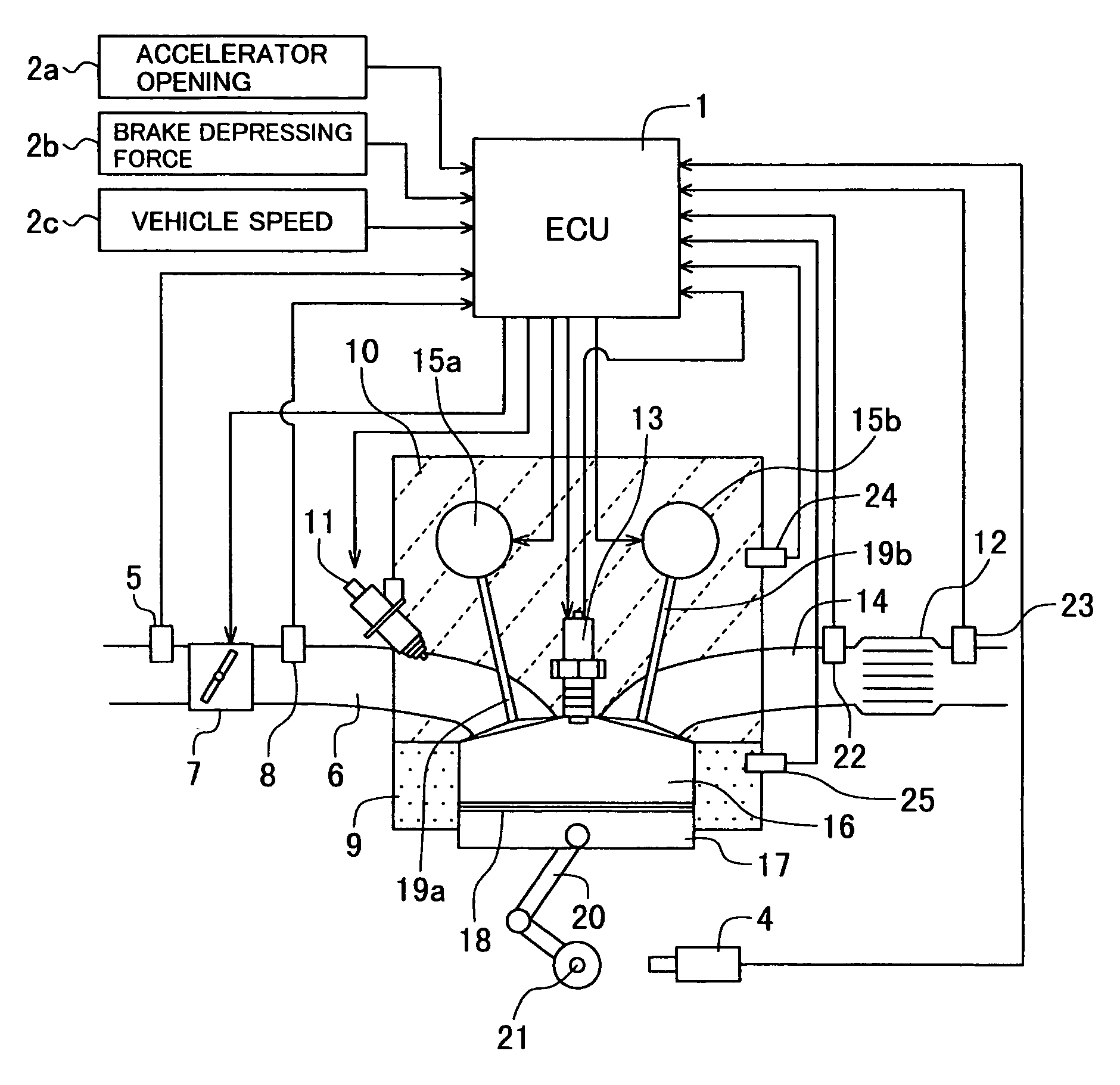
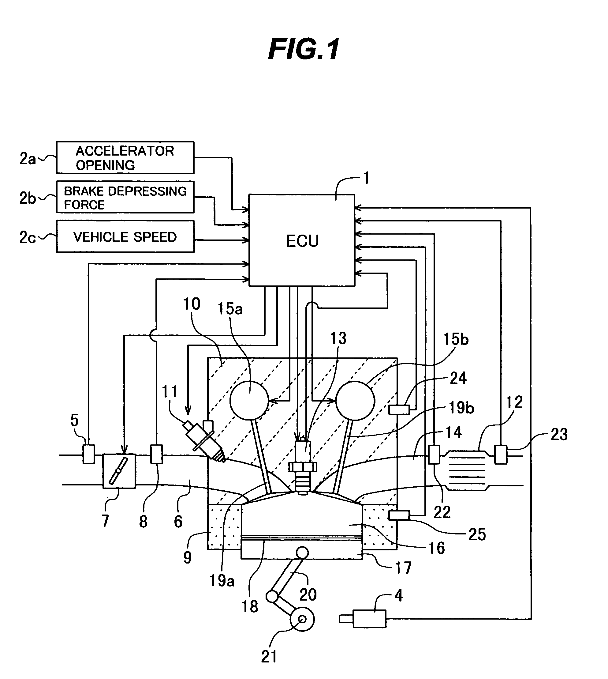
[0052]FIG. 1 is a system block diagram showing the configuration of the compression ignition internal combustion engine according to the first embodiment of the present invention.

[0053]The compression ignition internal combustion engine according to the embodiment can operate by switching between a spark ignition combustion using an ignition device and a compression ignition combustion self-igniting a fuel-air mixture by piston compression.

[0054]A combustion chamber 16 is formed in a space enclosed by a cylinder block 9, a piston 17 and a cylinder head 10. Reciprocating motion of the piston 17 is transmitted to a crank shaft 21 through a connecting...

second embodiment

[0179]Then, with reference now to FIG. 15 to FIG. 23, a configuration and operation of a compression ignition internal combustion engine according to the present invention will be explained below.

[0180]The configuration of the compression ignition internal combustion engine according to the embodiment is the same as that shown in FIG. 6. The embodiment changes control over the throttle valve and the variable valve mechanisms according to the operating condition of the engine in the compression ignition combustion mode.

[0181]First, the method of controlling the compression ignition combustion mode of the compression ignition internal combustion engine according to the embodiment in a low-speed, low-load state will be explained by using FIG. 15 to FIG. 17.

[0182]FIG. 15 is a flow chart showing the contents of control in the compression ignition combustion mode in a low-speed, low-load state of the compression ignition internal combustion engine according to the second embodiment of the...

third embodiment

[0221]Then, with reference now to FIG. 24 to FIG. 27, a configuration and operation of a compression ignition internal combustion engine according to the present invention will be explained below.

[0222]The configuration of the compression ignition internal combustion engine according to the embodiment is the same as that shown in FIG. 6. The embodiment switches between a compression ignition combustion mode and a spark ignition combustion mode according to the engine speed and engine load.

[0223]FIG. 24 is a flow chart showing the contents of control of switching between a compression ignition combustion mode and a spark ignition combustion mode of a compression ignition internal combustion engine according to a third embodiment of the present invention. Furthermore, FIG. 25 and FIG. 26 illustrate control of switching between a compression ignition combustion mode and a spark ignition combustion mode of the compression ignition internal combustion engine according to the third embodi...


PUM


Abstract

A control apparatus operates a compression ignition internal combustion engine by switching between spark ignition combustion using an ignition device and compression ignition combustion which self-ignites a mixture by piston compression. Variable valve mechanisms vary at least one of the valve timings and valve lifts of an intake valve and an exhaust valve. Intake air is regulated to vary the amount of air intake into a combustion chamber on the upstream side of a combustion chamber inlet of the compression ignition internal combustion engine. The variable valve mechanisms and the intake air regulation are controlled during the compression ignition combustion so as to perform the compression ignition combustion.

Description

TECHNICAL FIELD[0001]The present invention relates to a compression ignition internal combustion engine, and more particularly, to a compression ignition internal combustion engine capable of switching a compression ignition combustion and a spark ignition combustion.BACKGROUND ART[0002]As described in JP-A-10-56413, a compression ignition internal combustion engine adopts a combustion system of compressing and self-igniting a uniformly premixed fuel-air mixture. The compression ignition internal combustion engine can operate in an ultra-lean area (air-fuel ratio of 80 or more) that cannot be operated by a conventional gasoline engine or diesel engine, and decreases flame temperatures and realizes ignition combustion with a uniform fuel-air mixture, and therefore it is an engine that allows drastic reduction of both NOx and soot.[0003]Generally, when a fuel-air premixture is compressed and reached at a certain temperature, a reaction called “low temperature oxidation reaction” whose...

Claims


Application Information

Patent Timeline
IPC IPC(8): F01L1/34B60T7/12F02B1/12F02B3/06F02B11/00F02B77/08F02D13/02F02D41/00F02D41/06F02D41/12F02D41/18F02D41/30F02M25/07
CPCF02B11/00F02B77/085F02D13/0207F02D13/0257F02D13/0276F02D35/028F02D41/0002F02D41/006F02D41/062F02D41/18F02D41/3035F02D41/3064F02D41/307F02D41/3076F02M25/0752F02B1/12F01L2800/00Y02T10/47F02B3/06F02D41/123F02D2041/001F02D2041/002F02M25/0715Y02T10/18Y02T10/42F02M26/01F02M26/13Y02T10/12Y02T10/40
Inventor YAMAOKA, SHIRONOGI, TOSHIHARUOOSUGA, MINORUSHIRAISHI, TAKUYANAKAGAWA, SHINJIKIHARA, YUUSUKE
Owner HITACHI LTD
Why Eureka
Try Eureka