Method and apparatus for spine joint replacement

a spine joint and joint replacement technology, applied in the field of surgical devices and methods, can solve the problems of reducing function, limiting range, and causing debilitating pain, and achieve the effect of low friction

a spine joint and joint replacement technology, applied in the field of surgical devices and methods, can solve the problems of reducing function, limiting range, and causing debilitating pain, and achieve the effect of low friction

US7090698B2Inactive Publication Date: 2006-08-15GLOBUS MEDICAL INC +1

Image

  • Method and apparatus for spine joint replacement
  • Method and apparatus for spine joint replacement
  • Method and apparatus for spine joint replacement

Examples


Embodiment Construction

Disc Prosthesis and Single Facet Prosthesis

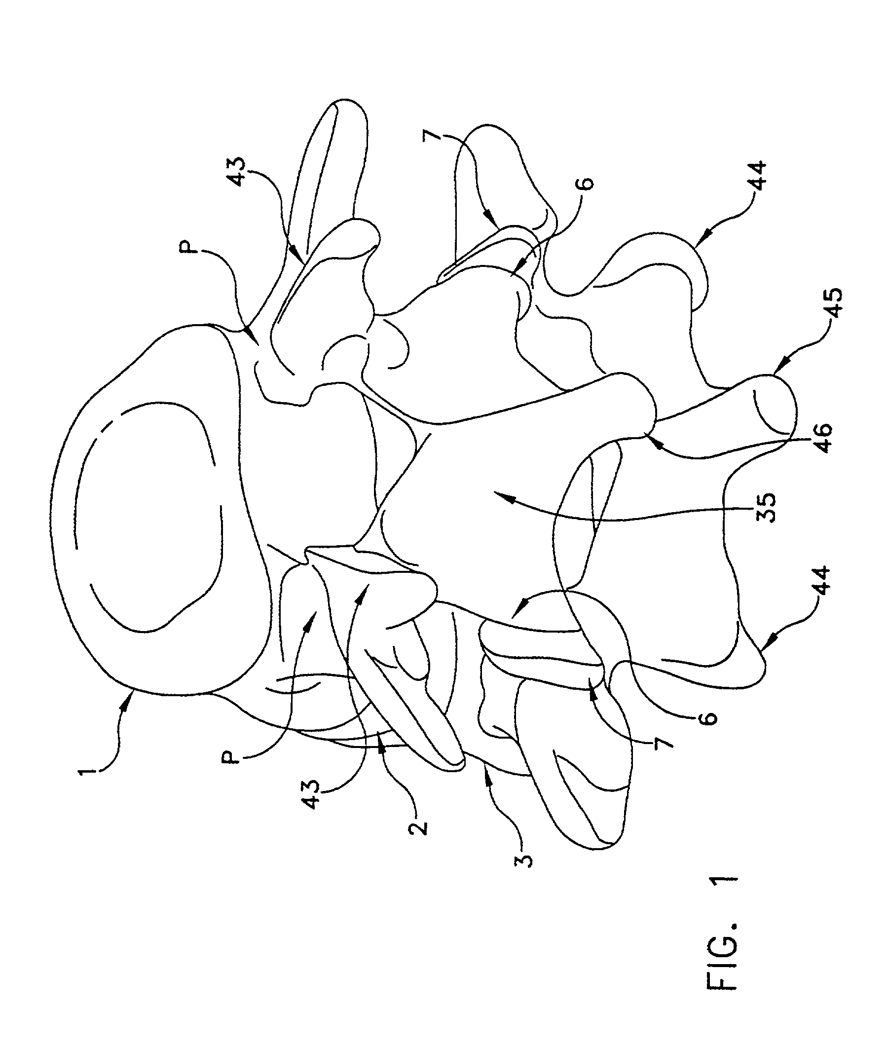
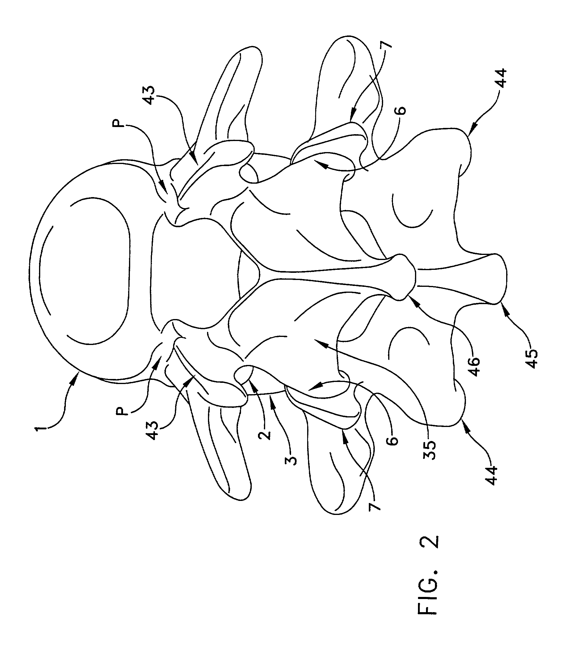
[0081]Referring now to FIGS. 1 and 2, there is shown a superior vertebra 1 and an inferior vertebra 3, with an intervertebral disc 2 located in between. Vertebra 1 has superior facets 43, inferior facets 6, posterior arch 35 and spinous process 46. Vertebra 3 has superior facets 7, inferior facets 44, posterior arch 36 and spinous process 45.

[0082]Referring now to FIG. 3, in accordance with one aspect of the present invention, the intervertebral disc 2 has been replaced by an artificial disc AD. This artificial disc AD may be a device such as is described by Stefee et al. in U.S. Pat. No. 5,071,437; Gill et al. in U.S. Pat. No. 6,113,637; Bryan et al. in U.S. Pat. No. 6,001,130; Hedman et al. in U.S. Pat. No. 4,759,769; Ray in U.S. Pat. No. 5,527,312; Ray et al. in U.S. Pat. No. 5,824,093; Buttner-Janz in U.S. Pat. No. 5,401,269; and Serhan et al. in U.S. Pat. No. 5,824,094; all which documents are hereby incorporated herein by reference. A...


PUM


Abstract

A prosthesis for the replacement of the cartilaginous structures of a spine motion segment is described. The prosthesis comprises an intervertebral disc prosthesis in combination with a facet joint prosthesis.

Description

REFERENCE TO PENDING PRIOR PATENT APPLICATIONS[0001]This patent application claims benefit of:[0002](1) pending prior U.S. Provisional Patent Application Ser. No. 60 / 273,031, filed Mar. 2, 2001 by E. Marlowe Goble et al. for TOTAL SPINE JOINT REPLACEMENT;[0003](2) pending prior U.S. patent application Ser. No. 09 / 726,169, filed Nov. 29, 2000 by E. Marlowe Goble et al. for FACET JOINT REPLACEMENT;[0004](3) pending prior U.S. patent application Ser. No. 09 / 736,103, filed Dec. 13, 2000 by E. Marlowe Goble et al. for MULTIPLE FACET JOINT REPLACEMENT; and[0005](4) pending prior U.S. patent application Ser. No. 09 / 797,309, filed Mar. 01, 2001 by T. Wade Fallin et al. for PROSTHESIS FOR THE REPLACEMENT OF A POSTERIOR ELEMENT OF A VERTEBRA.[0006]The four above-identified patent applications are hereby incorporated herein by reference.FIELD OF THE INVENTION[0007]This invention relates to surgical devices and methods in general, and more particularly to surgical devices and methods for replac...

Claims


Application Information

Patent Timeline
15 Aug 2006
Publication
US7090698B2
IPC
A61F2/44; A61B17/86; A61F2/00; A61F2/30
CPC
A61F2/4405; A61B17/86; A61F2310/00634; A61F2/442; A61F2002/30168; A61F2002/30177; A61F2002/30578; A61F2002/30708
Inventors
GOBLE, E. MARLOWE; FALLIN, T. WADE