Wavelength manipulation system and method

a wavelength manipulation and wavelength technology, applied in the field of optical switching systems, can solve the problems of narrow optical channel dispersion and loss, inability to dynamically reconfigure channel spacing, and inability to scale easily to multiple ports

Active Publication Date: 2006-08-15
II VI DELAWARE INC
View PDF8 Cites 99 Cited by
  • Summary
  • Abstract
  • Description
  • Claims
  • Application Information

AI Technical Summary

Benefits of technology

[0024]It is an object of the present invention to provide for an improved form of optical switching system.

Problems solved by technology

This is an optical power intensive architecture, which can provide for channel equalization and reconfiguration of wavelength selectivity, but is not scalable to multiple ports, has very high loss and because of the many auxiliary components such as wavelength tuneable filters has a large power and footprint requirement.ii) Wavelength switches have been proposed for OADMs, but do not naturally provide for channel equalization, the channel by channel switching in general leads to dispersion and loss narrowing of optical channels, and in the case of multiple port switches it is generally not possible to switch between ports without causing impairment (a hit) on intermediate ports.
In addition the channel spacing cannot be dynamically reconfigured.
Tuneable 3-port filters have also been proposed having a lack of impairment to the express paths but do not scale easily to multiple ports and may suffer from transient wavelength hits during tuning.
In addition poor isolation of tuneable 3 ports means they are less applicable to many add / drop applications which demand high through path isolation.
Usually two arrays of these mirrors are required to couple the light efficiently and because of the high degree of analogue control required structures based on this technology have proved to be extremely difficult to realize in practice and there are few examples of commercially successful offerings.
The trade-off is that in general the switching is more limited, with most implementation demonstrated to date being limited to small port counts—and the routing between ports is not arbitrary.
The difficulty with this approach has been that to achieve the wavelength resolution required when the angular dispersion is mapped to a displacement.
In addition, the number of ports is limited in each of these cases by the numerical aperture of the fiber as each of the different switch positions are discriminated by angles.
One approach that can be used is to decrease the numerical aperture through the use of thermally expanded cores or micro lenses—but this is done at the expense of wavelength resolution.
Obviously this is most appropriate to switching between 2 ports corresponding to the 2 polarisation states—so is not readily scalable, though more complicated schemes can be envisaged to allow for switching between multiple ports.
With polarization switching, the dynamic equalization of channels can be done at the expense of the rejected light being channelled into the second fibre—so it is not applicable to equalization of the express path whilst dropping a number of wavelengths.

Method used


Image

  • Wavelength manipulation system and method
  • Wavelength manipulation system and method
  • Wavelength manipulation system and method

Examples


first embodiment

[0054]In a first embodiment, the Liquid Crystal Display device is utilised to form a reflective diffraction grating such that, as illustrated in FIG. 3, input light 30 is output selectively either in a fully reflective manner 31, to the first order 32, 33 or to the second orders 34, 35.

[0055]The cells of the Liquid Crystal structure can be driven so as to select the output order. FIG. 5–FIG. 9 illustrates one form of the various possible driving arrangements for the 8 cells. In a first arrangement in FIG. 5, designed to produce a 0.0955 first order deflection, the driving state can be as illustrated 52 with the states being 0,0,1,1,2,2,3,3. In FIG. 6, for the negative first order 60, the driving states can be 3,3,2,2,1,1,0,0. In FIG. 7, for the second order output 70, the driving states 71 can be 0,1,2,3,0,1,2,3. Next in FIG. 8, for the negative second output order 80, the driving states 81 can be 3,2,10,3,2,1,0. Finally, in FIG. 9, for the purely reflective state 90, the driving st...

third embodiment

[0088]In a third embodiment the same objective is achieved efficiently employing a micro arrays of cylindrical lenses. The arrangement can be as illustrated in FIG. 11

[0089]In this case, there is provided an input array (in the x axis) of 2 fibres (101 and 102) and output array of 2 fibres (103 and 104) with a fibre spacing of 250 microns. The output of the fibres is coupled into a first micro cylindrical lens (110) to modify the divergence of the beam. The output is then coupled into an x-axis array of cylindrical lenses (111) with a separation corresponding to the fibre separation. The focal length of the lens 111 is chosen to be 500 micron so as to form a collimated beam of approximately 100 micron diameter. This beam is split in the x direction into two polarization states by a walk off crystal (112) of thickness 1.25 mm and then equalized in polarization by the polarization diversity optics 113 which can comprise an array of waveplates having a spacing of 125 microns. The outpu...


PUM


Abstract

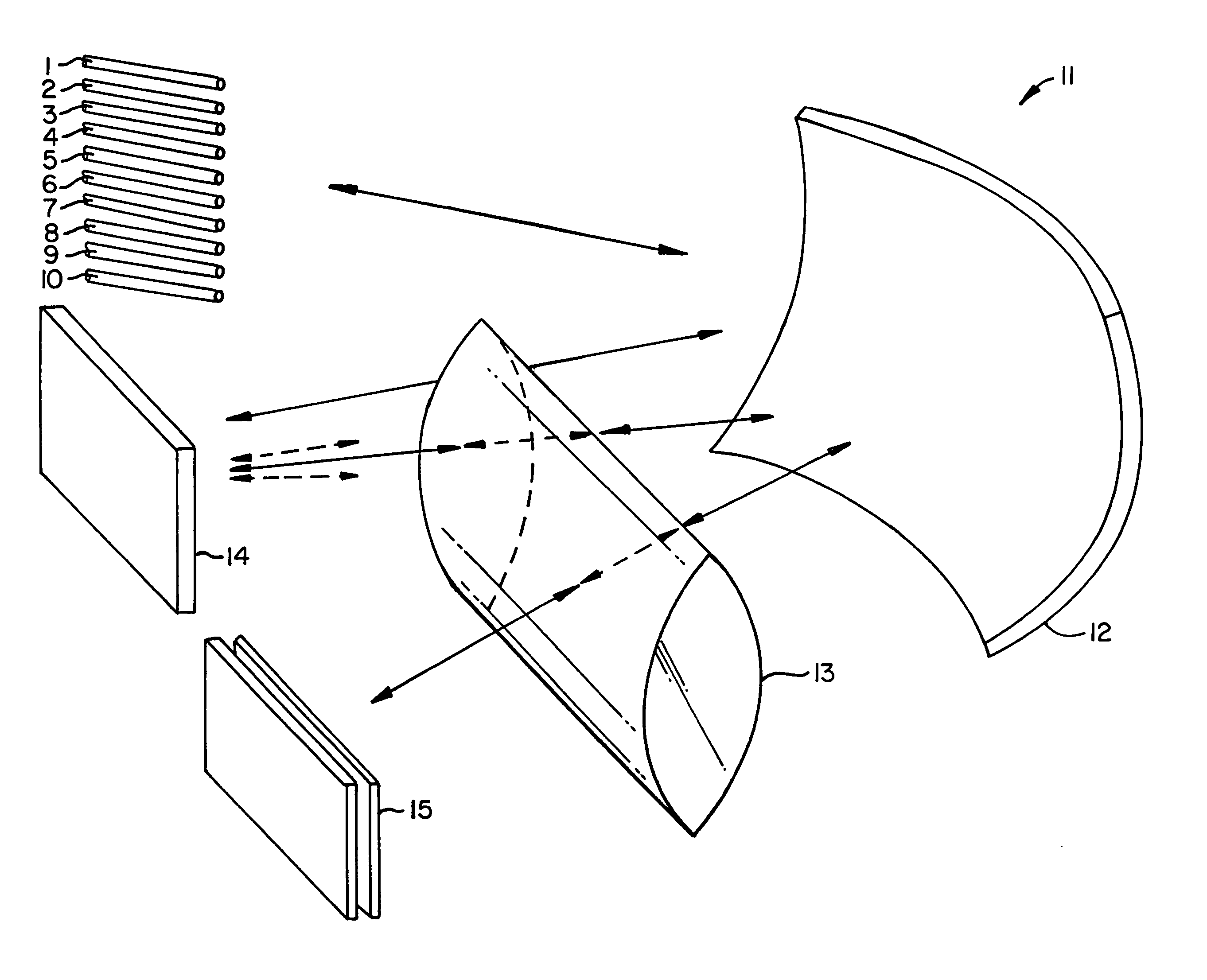
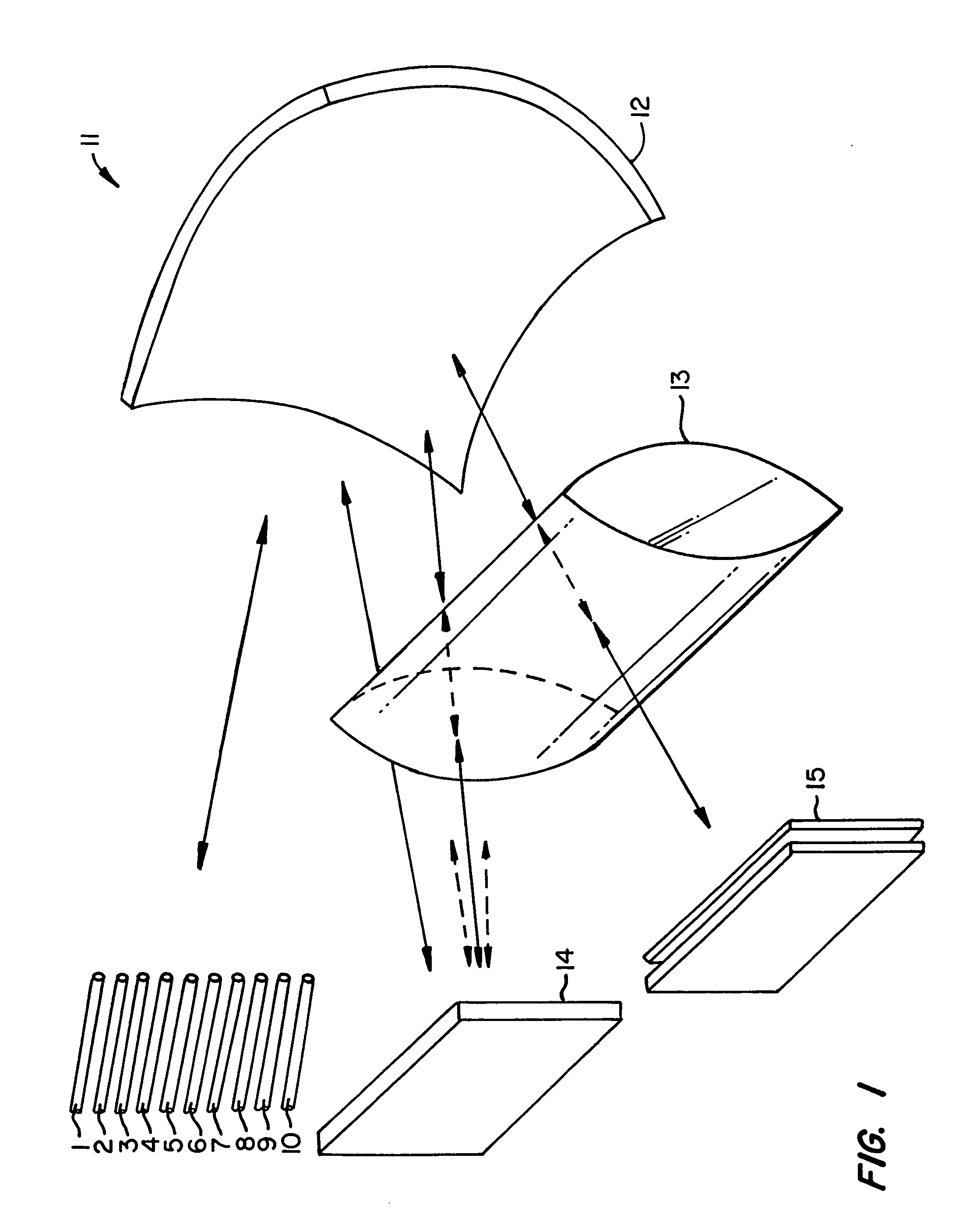
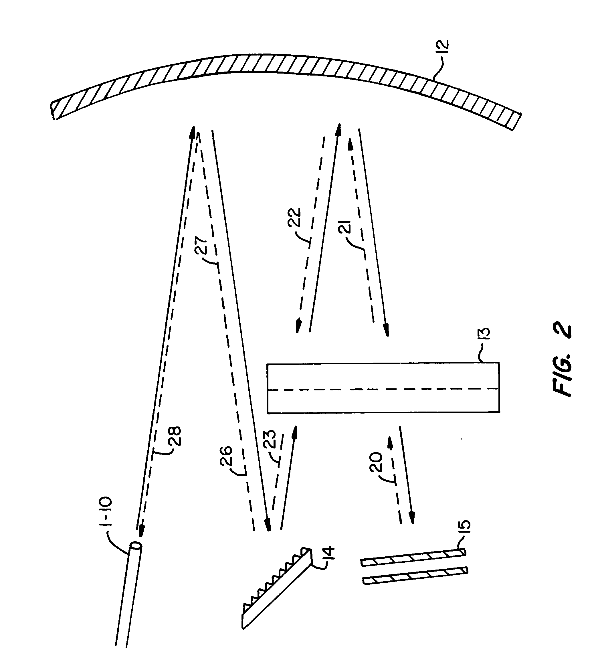
A wavelength selective manipulation device and method including: at least a first optical input port for inputting an optical signal including a plurality of wavelength channels; a first wavelength dispersing element for angularly dispersing the wavelength channels of the optical signal into angularly dispersed wavelength signals; an optical power element for focussing in the angularly dispersed dimension the angularly dispersed wavelength signals into a series of elongated spatially separated wavelengths bands; a spatial manipulation element for selectively manipulating the spatial characteristics of the spatially separated wavelength bands to produce spatially manipulated wavelength bands.

Description

FIELD OF THE INVENTION[0001]The present invention relates to an optical switching systems and, in particular, discloses a wavelength selective switch having possible attenuation control characteristics.BACKGROUND OF THE INVENTION[0002]In optical communications systems, the use of wavelength selective switching for applications of optical cross-connects has attracted much interest because of the goal of fully flexible, networks where the paths of each wavelength can be reconfigured to allow arbitrary connection between nodes with the capacity appropriate for that link at a particular point in time. Although this goal is still valid, it is clear that optical networks will evolve to this level of sophistication in a number of stages—and the first stage of the evolution is likely to be that of a reconfigurable add / drop node where a number of channels can be dropped and added from the main path, whose number and wavelength can be varied over time—either as the network evolves or dynamica...

Claims


Application Information

Patent Timeline
Patent Type & Authority Patents(United States)
IPC IPC(8): G02B6/34G02B6/293G02B6/00G09G3/36H04J14/02
CPCG02B6/2931G02B6/29311G02B6/29395G09G2310/06G09G3/36G02B6/29313
Inventor FRISKEN, STEVEN JAMES
Owner II VI DELAWARE INC
Why Eureka
Try Eureka