Method for operating a compressor

a compressor and compressor technology, applied in the field of compressor operation, can solve the problems of limited applicability of the method to sufficiently warm, no increase in air mass flow in this way, water loss, etc., and achieve the effect of easy improvement of efficiency

Inactive Publication Date: 2006-08-22
ANSALDO ENERGIA SWITZERLAND AG
View PDF27 Cites 46 Cited by
  • Summary
  • Abstract
  • Description
  • Claims
  • Application Information

AI Technical Summary

Benefits of technology

[0008]The present invention thus relates to providing a method for operating a compressor with which the efficiency can be increased easily while avoiding the disadvantages known from the state of the art.
[0013]Furthermore, it is advantageous for this invention if the intermediate cooling due to water spraying presented here takes place downstream from the low pressure part of the compressor at a pressure level below 3 bar. This is important to avoid greater losses of efficiency of the system as a whole despite the dissipation of heat to the outside. To ensure adequate cooling, the liquid medium may advantageously be sprayed in the intermediate cooler at a temperature of less than 5° C.

Problems solved by technology

Use of water for inlet cooling limits the applicability of the method to sufficiently warm ambient temperatures at which there is no risk of freezing (approx.
In contrast with inlet cooling, however, no increase in the air mass flow is achieved in this way.
A considerable disadvantage of intermediate cooling by evaporation is the water loss.
The liquid water sprayed in cannot in most cases be recovered economically from the exhaust and is discharged into the atmosphere.
This can be a considerable problem, especially in regions of water shortage.
With this type of intermediate cooling there are also technical problems due to the presence of liquid water in the compressor blades.
This can lead to erosion and corrosion and also alters the aerodynamic properties of the blades.

Method used


Image

  • Method for operating a compressor
  • Method for operating a compressor
  • Method for operating a compressor

Examples


Embodiment Construction

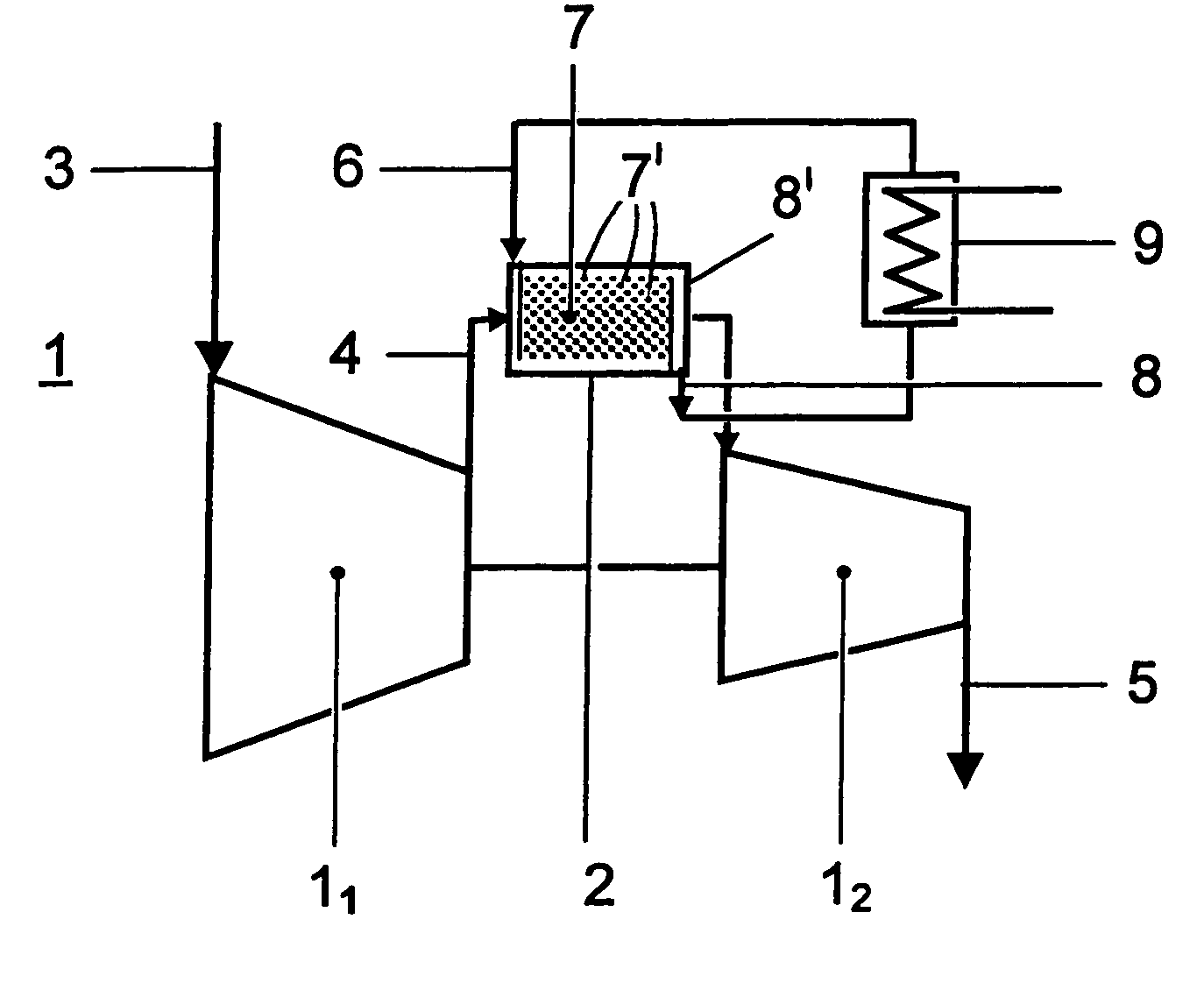
[0019]As shown in FIG. 1, the invention is based on a compressor 1 having an intermediate cooler 2 which is situated between two compressor stages 11, 12. Inlet air 3 flows into the first compressor stage 11 which constitutes the low pressure part of the compressor 1. The partially compressed air 4 discharged from the compressor stage 11 is cooled in the intermediate cooler 2 before being compressed further in the second compressor stage 12 to yield a certain final pressure. The completely compressed air 5 is then introduced into the combustion chamber of a gas turbine (not shown here), for example, or used for some other suitable purpose.

[0020]According to this invention, the intermediate cooling in the intermediate cooler 2 is performed by spraying in water 6 so that the cooling is not induced or not exclusively by uptake of evaporation energy but instead the uptake of sensible heat makes a significant contribution. The addition of water 6 takes place at a suitable installation do...


PUM


Abstract

In a method of operating a compressor, a gaseous medium is compressed in a first compressor stage. The partially compressed medium is sent from the first compressor stage into an intermediate cooler where it is cooled before being directed into the second compressor stage where it is compressed further. A liquid medium is sprayed into the gaseous medium in the intermediate cooler so that a two-phase mixture with a liquid phase and a gaseous phase is formed in the intermediate cooler. The liquid phase is separated again before adding it to the second compressor stage.

Description

CROSS-REFERENCE TO RELATED APPLICATIONS[0001]This application is a continuation of the U.S. National Stage designation of co-pending International Patent Application PCT / EP03 / 50180 filed May 20, 2003, the entire content of which is expressly incorporated herein by reference thereto.FIELD OF THE INVENTION[0002]The present invention relates to a method for operating a compressor.BACKGROUND OF THE INVENTION[0003]Two different methods of increasing the power of gas turbines based on cooling the air mass flow are known from the state of the art. Cooling of the air mass flow received by the gas turbine results in an increased power output by the machine. The reasons include first the increased mass flow of air due to the cooling and the reduction in power consumption by a compressor at low entrance temperatures. Fundamentally two types of cooling are known: cooling the inlet air flowing into the compressor and intermediate cooling between the two separate compressor stages.[0004]For inlet...

Claims


Application Information

Patent Timeline
Patent Type & Authority Patents(United States)
IPC IPC(8): F25D17/06F02C7/143F04D29/58
CPCF02C7/1435F04D29/5846F05D2260/212
Inventor JIMENEZ HAERTEL, CARLOSDOEBBELING, KLAUS
Owner ANSALDO ENERGIA SWITZERLAND AG
Why Eureka
Try Eureka