Device and method for ferrofluid power generator and cooling system

a technology of which is applied in the field of devices and methods for ferrofluid power generator and cooling system, can solve the problems of increasing weight, consuming extra power, and always cooling, and achieves the effects of high spinning speed, high efficiency, and removal of waste hea

Inactive Publication Date: 2006-08-22
IND TECH RES INST
View PDF5 Cites 7 Cited by
  • Summary
  • Abstract
  • Description
  • Claims
  • Application Information

AI Technical Summary

Benefits of technology

[0010]The invention is to provide a new concept of heat dissipation, wherein the waste heat of a CPU is conducted to a specific working fluid by a high efficiency heat absorbing system. The fluid is heated to its boiling point to generate bubbles, which are inflated and in turn drive the nano-magnetic particles mixed in the fluid to pass through a micro-coil with high spinning speed. Not only may this method remove the waste heat to increase the working efficiency of the system, but is also may reuse the waste heat to generate electric power.

Problems solved by technology

Micro electronic devices have a huge impact on companies and systems because they added chip functions within a common space causing increased heat, which is a big challenge to the engineers and researchers.
For either a personal computer or notebook, cooling is always an issue.
Although cooling fans are already installed on a typical computer, they increase weight, consume extra power, and are not very effective.
For a CPU (central processing unit) made by either INTEL or AMD, cooling must be done effectively, or the computer will become unstable, dead, or even burnt.
Therefore, an interior of the notebook is always very limited.
The higher the processing speed, the more power consumed by CPU.
Currently, for most notebooks, a CPU-attached fan (as shown in FIG. 1) and a system fan are installed, but for notebooks with Pentium 4 CPU, this method is not only power consuming (the consuming power ranges from 1.6 W to 7.7 W, the average is around 4.5 W) but also very noisy (the level of noise is around 39 dBA).
Furthermore, the poor cooling efficiency of this type of cooling fan is far from perfect (cooling efficiency is only 0.1 W / cm2) because of the limited heat-dissipation capacity of forced convection.

Method used


Image

  • Device and method for ferrofluid power generator and cooling system
  • Device and method for ferrofluid power generator and cooling system
  • Device and method for ferrofluid power generator and cooling system

Examples


Embodiment Construction

[0027]The device for ferrofluid power generator and cooling system of the preferable embodiments according to the invention is described thereinafter, but its actual layout does not have to completely match the description of the system design. Those who are familiar with such technique may have variations or modifications within the spirit and scope of the invention.

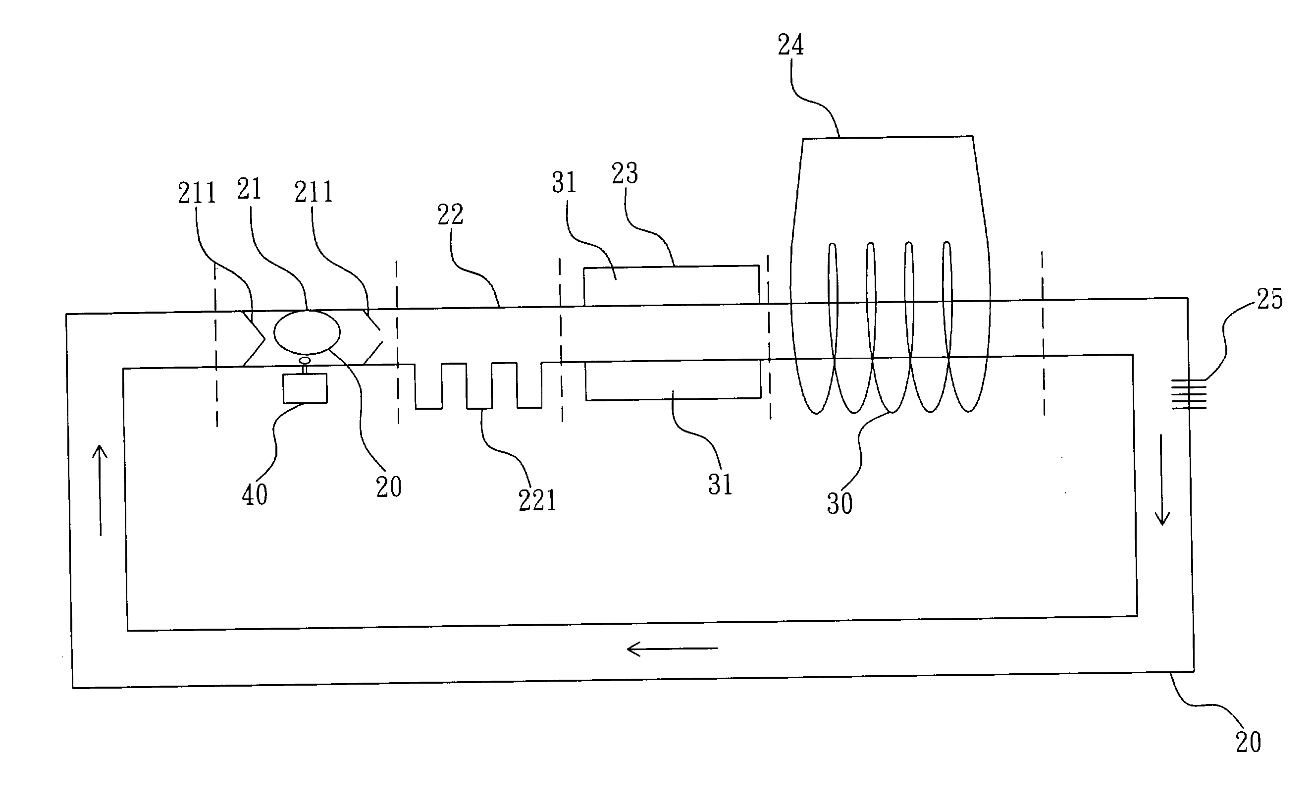
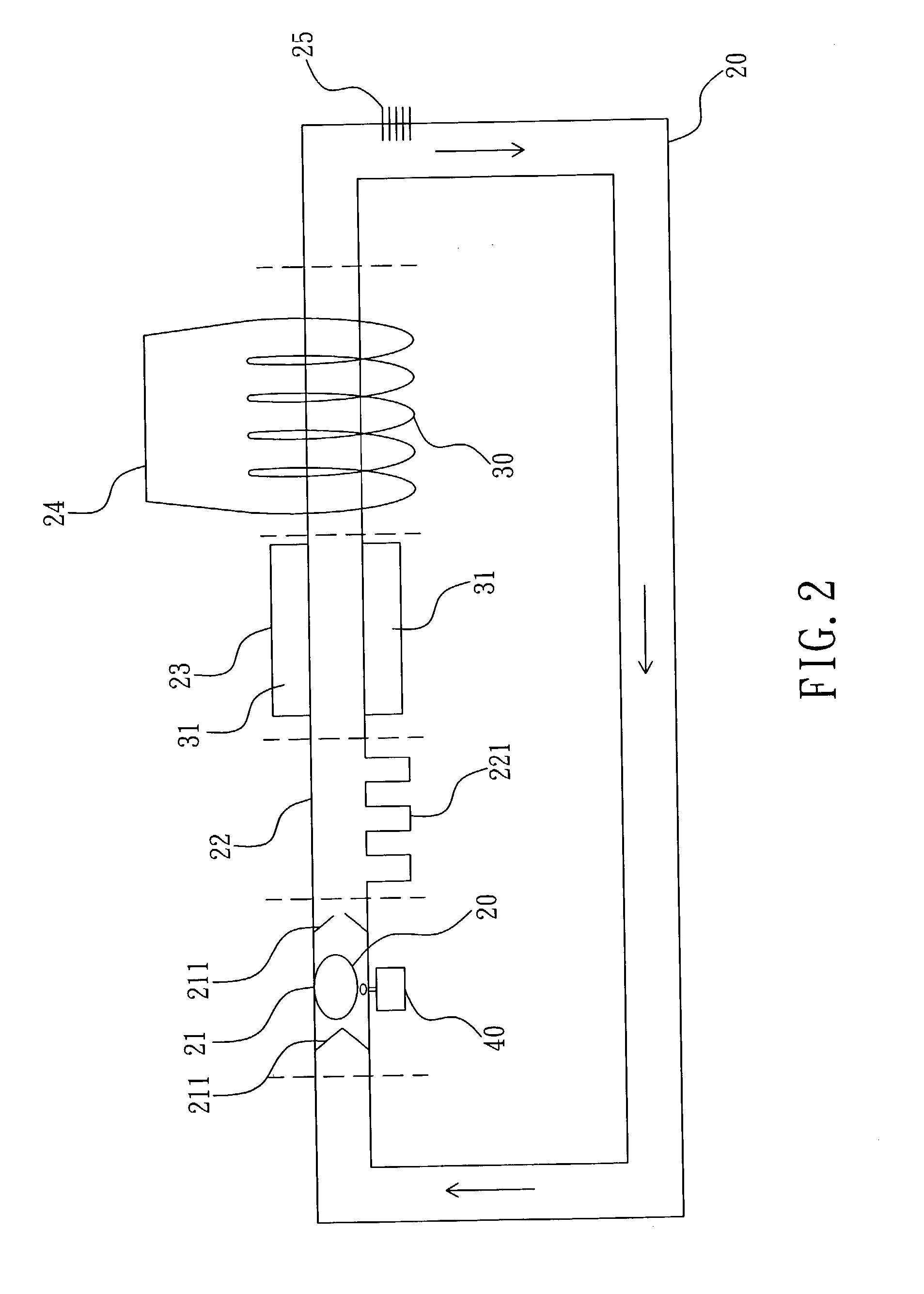
[0028]FIG. 2 is an illustration of the preferable basic layout of a device for ferrofluid power generator and cooling system according to the invention. THE invention includes a pipe system 20 and a coil 30. The pipe system 20 is connected to an electronic device 40 (a central processing unit abbreviated as CPU is taken as an example hereinafter) that generates waste heat. The coil 30 is wound around part of the pipe system 20 which is a closed loop filled with low boiling-point fluid (not shown in the drawings), and the magnetic particles (not shown in the drawings) are again contained in the fluid. When the heat is co...


PUM


Abstract

A device and method for ferrofluid power generator and cooling system, wherein the waste heat of electronic device is used as a heat source to vaporize fluid and form bubbles as a forwarding pump of the ferrofluid. The fluid with magnetic nano particles is pumped forward and rotated by a fluid mechanism, then passes through a high density coil to result in the time varying magnetic flux and induced current. No additional heat-dissipating device is needed for this invention to dispose the waste heat, which requires the waste heat to produce electricity, which provides cooling and saves power.

Description

BACKGROUND OF THE INVENTION[0001]1. Field of the Invention[0002]The invention relates to a device and method for ferrofluid power generator and cooling system, especially to a device and method applied to a ferrofluid power generator and cooling performed by the phase change of fluid that may remove waste heat generated from an electronic device.[0003]2. Description of the Prior Art[0004]Since IC was invented in 1959, IC fabrication technology has advanced tremendously. It is expected that an era of nano (nm) technology will come in the 21st century. Micro electronic devices have a huge impact on companies and systems because they added chip functions within a common space causing increased heat, which is a big challenge to the engineers and researchers. It is predictable that more functions embedded in a chip, require more cooling.[0005]For either a personal computer or notebook, cooling is always an issue. Although cooling fans are already installed on a typical computer, they inc...

Claims


Application Information

Patent Timeline
Patent Type & Authority Patents(United States)
IPC IPC(8): H02K9/00H02K44/08H01L23/473
CPCH01L23/473H01L2924/0002H01L2924/00
Inventor HSU, LI-CHIEH
Owner IND TECH RES INST
Why Eureka
Try Eureka