
Differential amplifier arrangement with current regulating circuit and method for operating a differential amplifier arrangement

a technology of current regulating circuit and differential amplifier, which is applied in differential amplifiers, amplifiers with semiconductor devices/discharge tubes, amplifier control details, etc., can solve problems such as signal distortion, reduce the accuracy of the “gain step”, and the accuracy of the gain stage is reduced, so as to achieve different accurate gains and increase the effect of the gain stag

Active Publication Date: 2006-08-22
WOLFSPEED INC
View PDF8 Cites 15 Cited by
  • Summary
  • Abstract
  • Description
  • Claims
  • Application Information

AI Technical Summary

Benefits of technology

This solution enhances the signal / noise ratio, maintains a large voltage swing, and allows for accurate switchable gains without altering the operating point, while reducing chip area and power losses, thus improving the overall performance of the receiver device.

Problems solved by technology

This prevents amplification of input signals with very high levels which overdrive the downstream signal-processing switching elements and thus cause signal distortions.
In the case of such switchable gains, however, the accuracy that can be achieved is problematic since most circuit concepts have a different operating point depending on the gain.
Changing the operating point in a manner dependent on the switchable gain reduces the accuracy of the “gain step”.
However, such combination is always associated with additional parasitic signals that influence the performance of the receiver.
A further problem is improving the signal / noise ratio in low-noise amplifiers.
However, the use of normal nonreactive load resistors instead of the coils L1 and L2 illustrated in the example leads to a higher voltage drop across the load resistors in the case of a large DC current.
It is therefore additionally necessary to increase the supply voltage, which, however, leads to additional power losses.
However, such an on-chip inductance requires a very large area on the chip and thus enlarges the receiver unit in a disadvantageous manner.

Method used


Image

  • Differential amplifier arrangement with current regulating circuit and method for operating a differential amplifier arrangement
  • Differential amplifier arrangement with current regulating circuit and method for operating a differential amplifier arrangement
  • Differential amplifier arrangement with current regulating circuit and method for operating a differential amplifier arrangement

Examples


Embodiment Construction

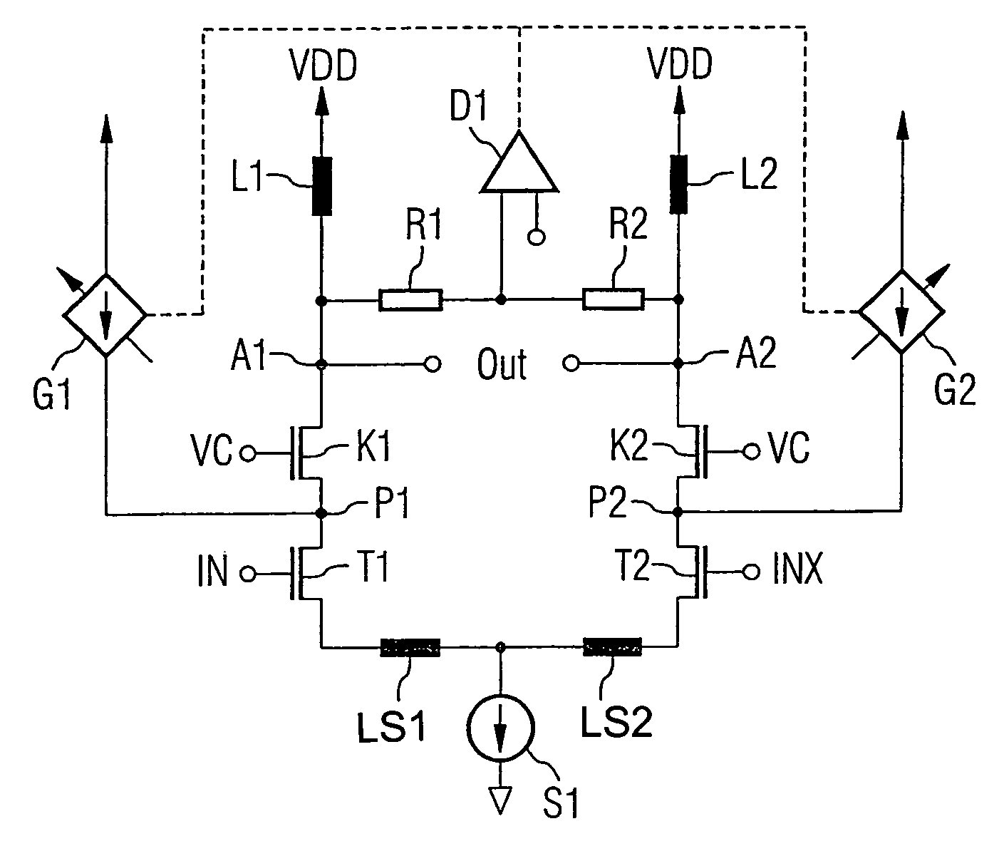
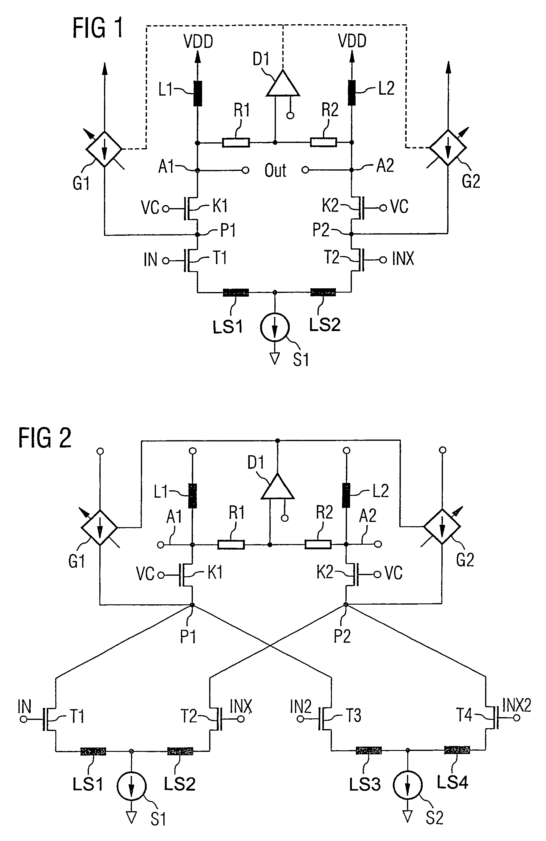
[0031]FIG. 1 is a schematic diagram of a differential amplifier arrangement having a common-mode current regulation in accordance with an aspect of the present invention.

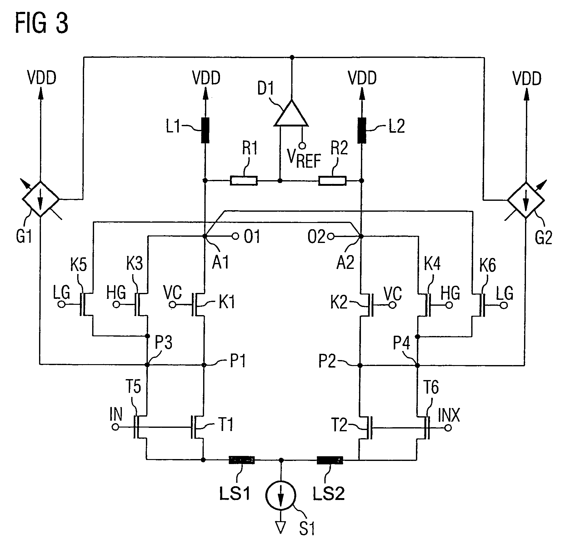
[0032]A DC current source S1 is connected via a coil LS1 to the source terminal of a field-effect transistor T1 of the n-channel type. A further source terminal of a second field-effect transistor T2 is likewise connected via a coil LS2 to the current source S1. The coils LS1 and LS2 serve for matching the two transistors T1 and T2. The control terminals of the field-effect transistors T1 and T2 form the inputs of the differential amplifier arrangement. They are designed for feeding the differential input signal IN and INX, respectively. The drain terminal of the first signal transistor T1 is connected to the source terminal of a second transistor K1 and also to the output of a regulable current source G1. The drain terminal of the transistor T2 is connected to the source terminal of a fourth transistor K2 and to th...


PUM


Abstract

Provision is made of a differential amplifier arrangement with a current source (S1), two controllable paths (T1, T2), which are in each case coupled by one terminal to the current source (S1) and the control terminals of which form the input of the differential amplifier arrangement. Via a respective cascode circuit (K1, K2), a load (L1, L2) is respectively connected to the first and second controllable paths (T1, T2). At least one tap (A1) between one of the loads and one of the cascode circuits forms an output of the differential amplifier arrangement. Provision is made of a comparison means (D1) having two inputs, which is designed for outputting a control signal dependent on a comparison. A first input is coupled to the first tap (A1) and the second input is designed for feeding a reference signal. Furthermore, the differential amplifier arrangement contains a regulable current source (G1), the control input of which is connected to the output of the comparison means and the current output of which is connected to the second terminal (P1) of at least the first controllable path (T1).

Description

REFERENCE TO RELATED APPLICATION[0001]This application claims the benefit of the priority date of German application DE 103 44 878.0, filed on Sep. 26, 2003, the contents of which are herein incorporated by reference in their entirety.FIELD OF THE INVENTION[0002]The invention relates to a differential amplifier arrangement with a current regulating circuit. The invention furthermore relates to a method for operating a differential amplifier arrangement.BACKGROUND OF THE INVENTION[0003]In receiving devices, a low-noise amplifier is usually situated such that it is connected directly downstream of the receiving antenna. Its task is to amplify an input signal received by the antenna. In this case, the amplifier is intended to have only a low inherent noise in order thus to have a good signal / noise ratio. In addition to the requirement for a low noise figure, a switchable gain is likewise desirable. This switchable gain is called “gain step”. This prevents amplification of input signals...

Claims


Application Information

Patent Timeline
Patent Type & Authority Patents(United States)
IPC IPC(8): H03F3/45H03G1/00
CPCH03F3/45654H03G1/0029H03F2200/372H03F2203/45302H03F2203/45316H03F2203/45318H03F2203/45371H03F2203/45311
Inventor ZIPPER, JOSEFSCHELMBAUER, WERNERSTOGER, CLAUS
Owner WOLFSPEED INC
Learn More