Apodization of beams in an optical interferometer

a beam and optical interferometer technology, applied in the field of interferometry, can solve the problems of reducing the signal of the photo-detector, reducing the resolution of the homodyne interferometer, and difficult to measure the change in distance significantly smaller, so as to avoid diffraction and reduce diffraction

Inactive Publication Date: 2006-08-22
LOCKHEED MARTIN CORP
View PDF9 Cites 18 Cited by
  • Summary
  • Abstract
  • Description
  • Claims
  • Application Information

AI Technical Summary

Benefits of technology

[0014]The present invention comprises an optical interferometer device having one or more apodization masks disposed along optical paths in the device. An aspect of the invention is the use of one or more apodization masks to shape one or more beams to produce shaped beams as needed. A shaped beam can include a first beam portion having apodized edges to reduce diffraction d...

Problems solved by technology

If the measurement beam is an odd multiple of a quarter of the wavelength longer, the beams add destructively, resulting in a reduced signal from the photo-detector.
The resolution of a homodyne interferometer is limited, as it is difficult to measure changes in distance significantly smaller than the laser wavelength (typically a half to several micrometers) due to intensity fluctuations of the laser.
When measuring distances with fine precision, various error sources can affect the results.
The laser radiation is often routed to the beam launcher by means of optical fibers, where small effects such as a temperature variation or a strain on the fiber can affect the apparent optical length of the fiber and can result in a phase change that erroneously appears to be a measured displacement of the fiducial ...

Method used


Image

  • Apodization of beams in an optical interferometer
  • Apodization of beams in an optical interferometer
  • Apodization of beams in an optical interferometer

Examples


Embodiment Construction

[0028]The following description of the present invention is presented with respect to a specific interferometer device that was under study at the time of the invention. However, it will be clear to one of ordinary skill, from the following discussion, that the present invention can be adapted for use in any kind of optical interferometer.

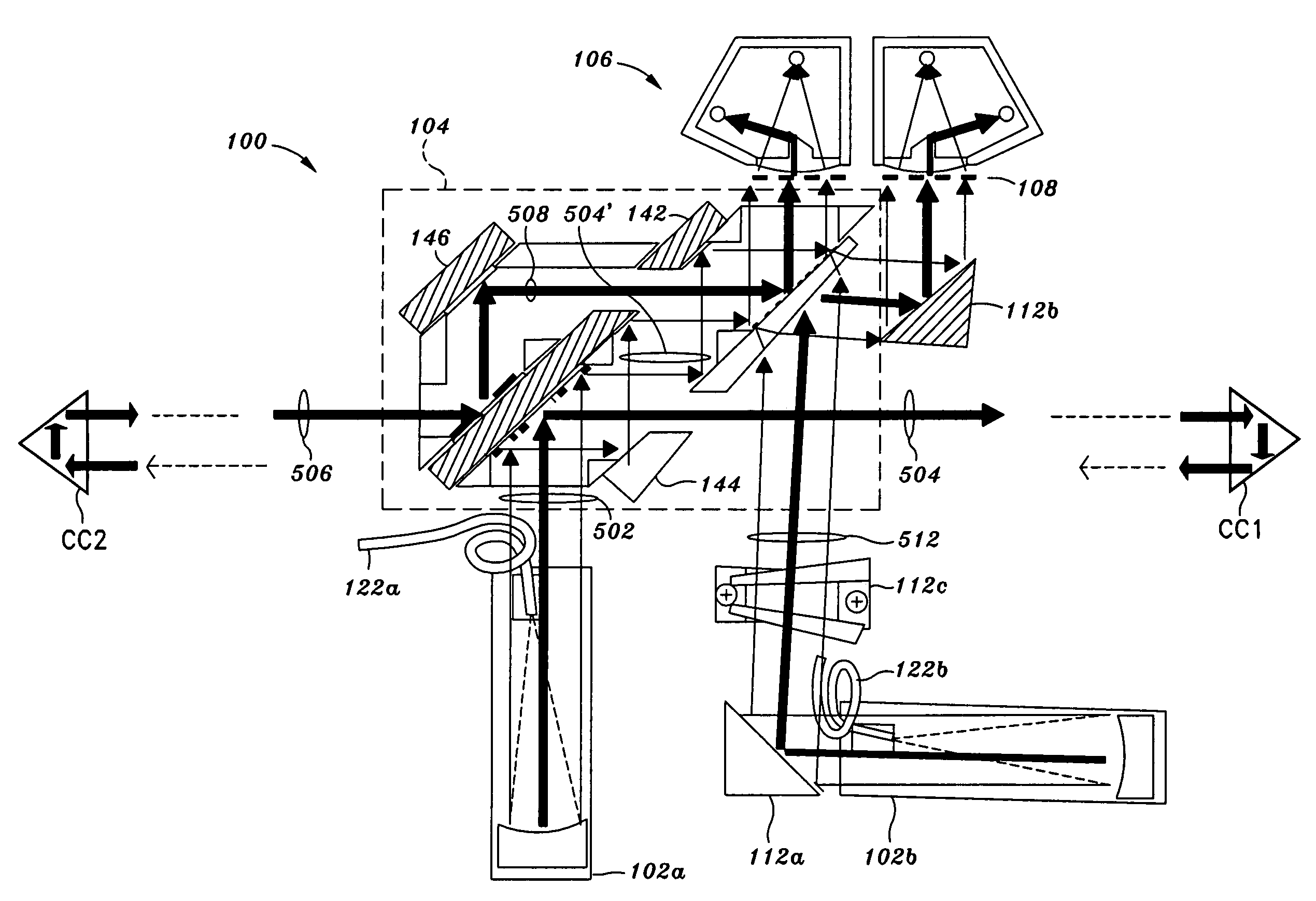
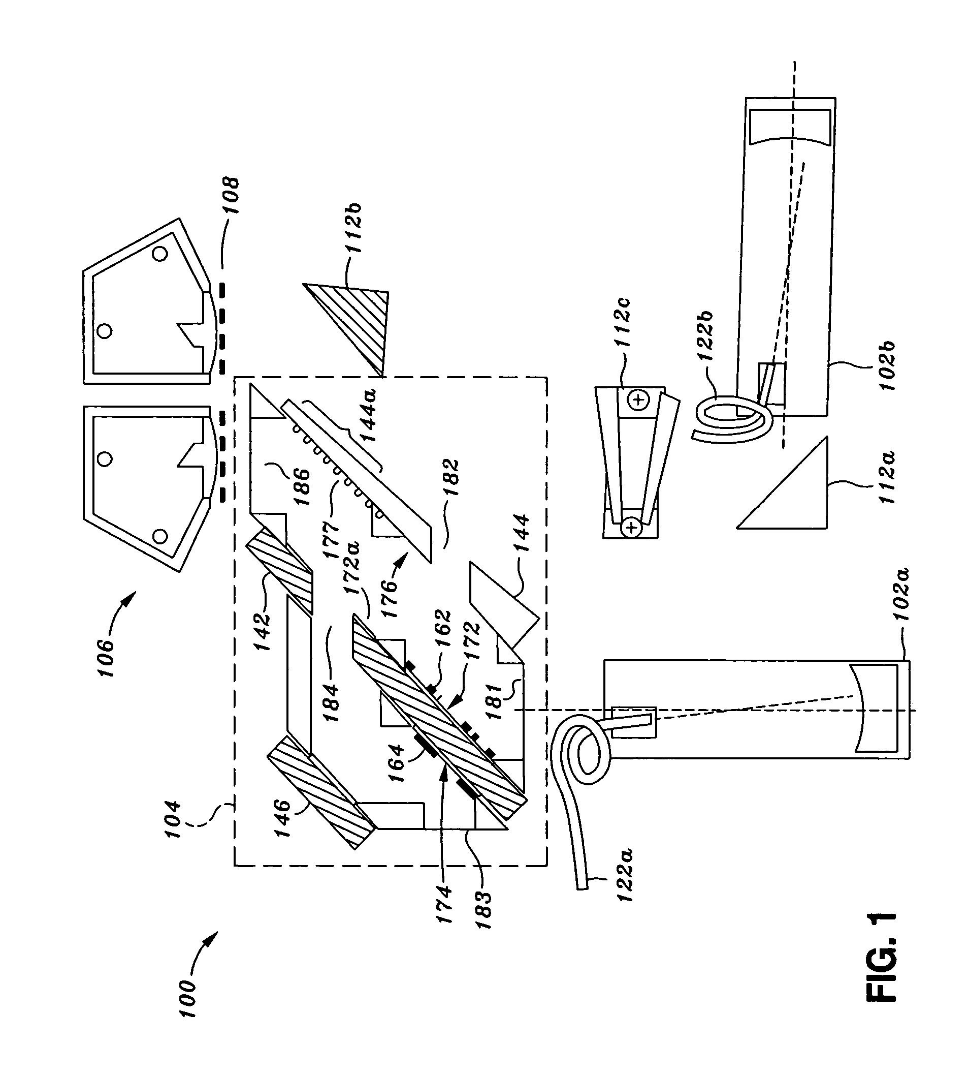
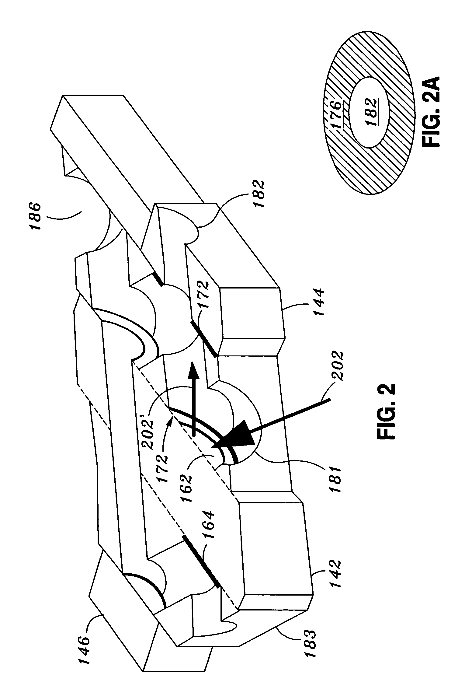
[0029]FIG. 1 shows the basic components of an optical interferometer in the context of a specific illustrative embodiment. The interferometer configurations that is shown in the figure is known as a “common path heterodyne interferometer” (CoPHI). The CoPHI interferometer shown in FIG. 1 operates is arranged in a “racetrack” (RT) configuration. A source beam directed to the optical component 104 is provided by a collimator 102a. In the specific embodiment shown, the collimator 102a is an off-axis parabolic collimator. This component is described in more detail in U.S. application Ser. No. 10 / 349,758. It can be appreciated of course that any other...


PUM


Abstract

An interferometry apparatus comprises one or more beam generators, a detector, and a plurality of optical paths along which one or more beams of light propagate. Disposed along at least one of the optical paths is an apodization mask to shape one of the beams.

Description

CROSS-REFERENCES TO RELATED APPLICATIONS[0001]The present invention claims priority to U.S. Provisional Application No. 60 / 449,995, filed Feb. 25, 2003 and is herein incorporated by reference for all purposes.[0002]The present invention is related to the following commonly owned, co-pending applications: U.S. application Ser. No. 10 / 180,086, filed Jun. 27, 2002), U.S. application Ser. No. 10 / 349,758, filed Jan. 22, 2003), U.S. application Ser. No. 10 / 293,209, filed Nov. 12, 2002), and U.S. application Ser. No. 10 / 787,662, concurrently filed herewith, entitled “A Symmetric Periscope, Concentric Beam Configuration for an Ultra-high Precision Laser Interferometric Beam Launcher”, each of which are herein incorporated by reference for all purposes.STATEMENT AS TO RIGHTS TO INVENTIONS MADE UNDER FEDERALLY SPONSORED RESEARCH OR DEVELOPMENT[0003]The U.S. Government has a paid-up license in this invention and the right in limited circumstances to require the patent owner to license others o...

Claims


Application Information

Patent Timeline
IPC IPC(8): G01B9/02
CPCG01B9/02003G01B9/02038G01B9/02057
Inventor AMES, LAWRENCE L.DUTTA, KALYAN
Owner LOCKHEED MARTIN CORP
Why Eureka
Try Eureka