Fuel transfer pump

a fuel transfer pump and fluid pump technology, applied in the direction of pump, positive displacement liquid engine, liquid fuel engine, etc., can solve the problems of increased risk of environmental danger, increased piping, inconvenient and dangerous area, etc., to save money, less inventory, and more flow

Inactive Publication Date: 2006-08-29
ENVIRON OPW
View PDF13 Cites 12 Cited by
  • Summary
  • Abstract
  • Description
  • Claims
  • Application Information

AI Technical Summary

Benefits of technology

[0035](5) Because the pump / motor is located in the manifold and not inside the tank, the 4″“riser pipe” (connects the pump to the 4″ tank bung) and the 2″“pipe column” can be supplied by the installing contractor and cut-to-length and threaded at the job site. The advantage is that the fuel transfer pump ships in one small square box (16″ W×16″H×16″ L) and not as a long piece of equipment like a submersible pump (typically 6 feet to 12 feet long). This also means one fuel transfer pump model can fit any diameter tank which is not the case with submersible pumps.
[0036](6) Because the fuel transfer pump has considerably more flow than a comparable suction pump or submersible pump one fuel transfer pump model can accommodate as few a one dispenser to as many as 10 dispensers (small and large service stations). This also means less inventory (saves money) for the stocking distributor or contractor.

Problems solved by technology

(1) It typically requires one pump per hose, or many pumps per fueling facility (typical is 12 suction pumps per fueling facility). Each pump requires its own piping run, which results in excessive piping and greater risk of an environmentally dangerous fuel leak through the additional pipe runs.
(2) Pumps are located inside the dispenser. This is an inconvenient and dangerous area to perform routine service work. Customers frequent the dispenser area and could be in danger or at unnecessary risk when the pumps are being serviced.
(3) Suction pumps commonly experience fuel vapor lock and can lose prime especially in warm temperatures or at high altitudes. When a pump loses prime, highly flammable fuel vapors are compressed and pumped through the system, increasing the chance of a dangerous explosion.
(4) Suction pump systems typically have lower flow rates than pressure type pumping systems and are not desirable for use at large fueling facilities with many fueling points.
The disadvantages of a of submersible type pressure pumps are as follows:
(1) Although a submersible pump can pump a higher volume of fuel than that of a fuel suction pump it can only supply about 6 nozzles at one time or a maximum of 65 gallons per minute. Many large fueling facilities exceed the capabilities of submersible pumps when several nozzles are activated simultaneously.
(2) A submersible pump's electric motor is dangerously submerged in the fuel located inside the fuel storage tank. Electric power inside the tank increases the potential of an explosion especially when the tank is low (due to increased fuel vapors).
(3) Locating the pump / motor inside the tank means that a long pump column is required to be installed at the factory and not in the field. The result is that the submersible pump is awkward to handle and ship (can be up to 15 feet long), more costly to ship, and thus more likely to incur shipping damage during transit and while handling.
(4) The fuel flow path through a submersible pump is restrictive and creates considerable friction loss. The electric motor is directly in the flow path with only a tiny gap around the outside of the motor for the fuel to pass by.
(5) A submersible pump / motor is inserted into the tank typically through a 4″ tank fitting. Therefore the outside diameter of the pump / motor must be smaller than the inside diameter of the tank fitting. This requires submersible pumps to use high aspect ratio electric motors (long and thin motors) which are inefficient. In addition these submersible pumps have small diameter impellers (less than 3.5″ in diameter) that are not designed for high flow output.
(6) A submersible pump motor has a “dry stator”. This means that the motor's stator is contained within a sealed stainless steel metal casing. Stainless steel is a non-magnetic metal which becomes a restrictive barrier between the stator and rotor which operates on electrically generated magnetic power. The stainless steel casing reduces the efficiency of the submersible pump motor because it retains heat and interferes with the magnetic motor.

Method used


Image

  • Fuel transfer pump
  • Fuel transfer pump
  • Fuel transfer pump

Examples


Embodiment Construction

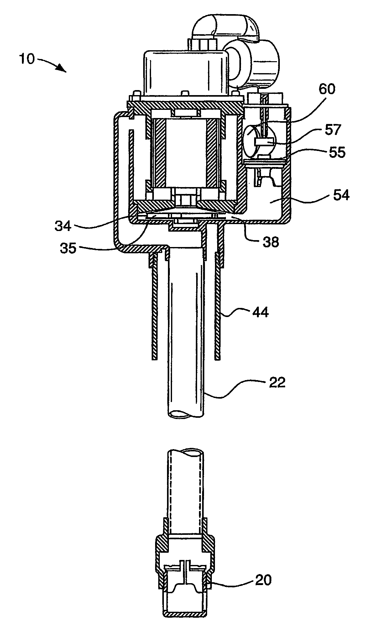
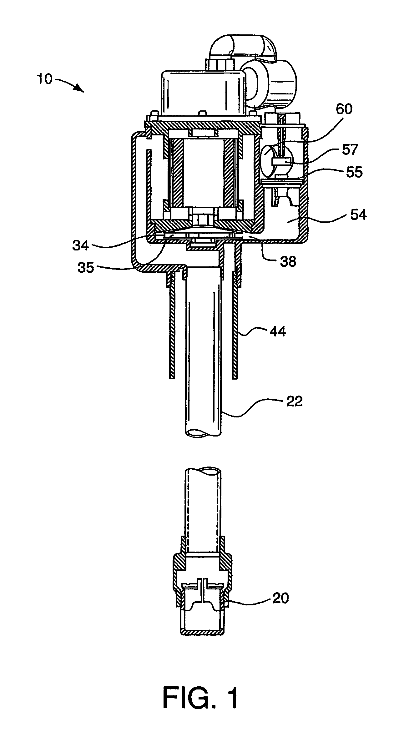
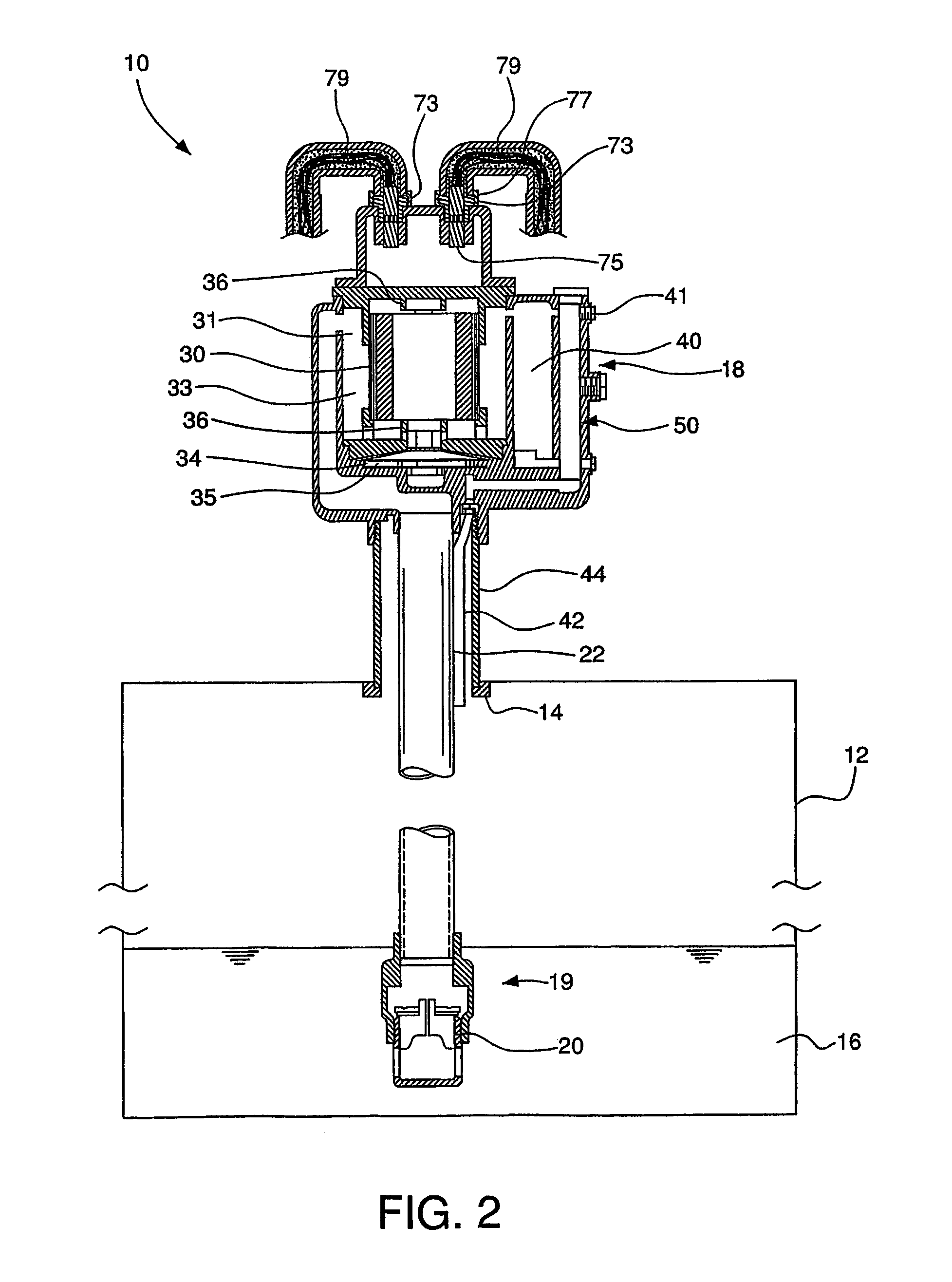
[0045]FIGS. 1 and 2 show a cross section through the fuel transfer pump 10 and storage container 12. FIG. 3 shows a top view of the fuel transfer pump. FIG. 4 shoes a perspective view of the fuel transfer pump, and FIGS. 5 and 6 show partial cross sections through the fuel transfer pump.

[0046]The fuel transfer pump 10 has a stand pipe 44, that is commonly a 4″ diameter pipe. The stand pipe 44 is connected to the bung 14 of the storage container in a leak resistant fit, and the stand pipe 44 supports the weight of the fuel transfer pump 10. A narrower diameter riser pipe / column 22 and a return pipe 42 are contained within the stand pipe 44 and extend into the tank 12. The end of the riser pipe / column 22 has an intake 19 ideally submerged within the combustible liquid or fuel 16 in the storage container 12. A foot valve 20 at the end of the riser pipe serves as a kind of check valve. The foot valve 20 prevents pipe flow in the direction of the tank 12, and thus insures that the fuel t...


PUM


Abstract

The fuel transfer pump is a combination suction and pressure pump in a manifold above the fuel storage tank. The fuel transfer pump is contained within a manifold. The pump is liquid cooled (more specifically, fuel cooled) and is located in a manifold above the fuel storage tank and not submerged inside the tank. The fuel transfer pump draws (using suction) the fuel up from the bottom of the tank though the pipe column into the manifold and then under pressure pumps it to one or more fueling dispensers.

Description

RELATED APPLICATIONS[0001]This application claims priority to U.S. Provisional Application Ser. No. 60 / 325,504 filed on Sep. 28, 2001.FIELD OF THE INVENTION[0002]This invention relates to the field of combustible fluid pumping systems, particularly those involving an underground storage tank and an aboveground combustible liquid dispenser.BACKGROUND OF THE INVENTION[0003]There are two principal types of fuel pumping systems. One is a suction type fuel delivery system and the other is a pressure type fuel delivery system.[0004]Suction type fuel pumps are the most common type of fuel delivery pump used outside of the United States. A suction pump is typically a positive displacement type pump housed inside the fueling dispenser. The fuel is drawn or sucked under negative pressure from the fuel storage tank through an underground piping system to a single fuel dispenser. For safety reasons, the fuel dispenser is often a substantial distance from the storage tank.[0005]The advantage of ...

Claims


Application Information

Patent Timeline
Patent Type & Authority Patents(United States)
IPC IPC(8): F04B17/03B67D7/04F04D9/00F04D13/06F04D29/58
CPCF04D9/008F04D29/588F04D13/06
Inventor STRUTHERS, KEVIN D.WEBB, MICHAEL C.
Owner ENVIRON OPW
Why Eureka
Try Eureka