Line loop back for very high speed application

a very high-speed, line loop back technology, applied in the direction of frequency-division multiplex, instruments, transmission monitoring, etc., can solve the problems of consuming large amounts of power, adversely affecting the jitter performance of normal mode transceiver operation, and inefficient and complex implementation of line loop back, etc., to achieve high-speed noise coupling effect and reduce noise coupling

Active Publication Date: 2006-08-29
AVAGO TECH INT SALES PTE LTD
View PDF9 Cites 25 Cited by
  • Summary
  • Abstract
  • Description
  • Claims
  • Application Information

AI Technical Summary

Benefits of technology

[0008]In order to overcome these problems, the present invention offers a novel approach that does not require such high-speed multiplexers and buffers. Once the serial data is received, clock is extracted and data is recovered. The recovered data is deserialized to low speed parallel data and clock. This low speed parallel clock and data are then looped back to the transmitter section to be serialized into high-speed serial data. The implementation according to the present invention is quite attractive for applications that already have clock and data recovery, and deserializer and serializer blocks, and therefore no additional high-speed blocks are required for loop-back. According to the present invention, all the multiplexers and buffers are low speed multiplexers and buffers.
[0009]An additional advantage of the implementation according to the present invention is that there are fewer high-speed blocks than the conventional implementation. High frequency noise travels much more easily through the substrate than low frequency noise, and hence the implementation according to the present invention has reduced noise coupling effects as compared to conventional implementations. Moreover, according to the present invention, not only is the link tested, but also the functionality of the transmitter and receiver are verified.

Problems solved by technology

Some conventional implementations of the line loop back are inefficient and complex, consume large amounts of power, and adversely affect the jitter performance of normal mode transceiver operation.

Method used


Image

  • Line loop back for very high speed application
  • Line loop back for very high speed application
  • Line loop back for very high speed application

Examples


Embodiment Construction

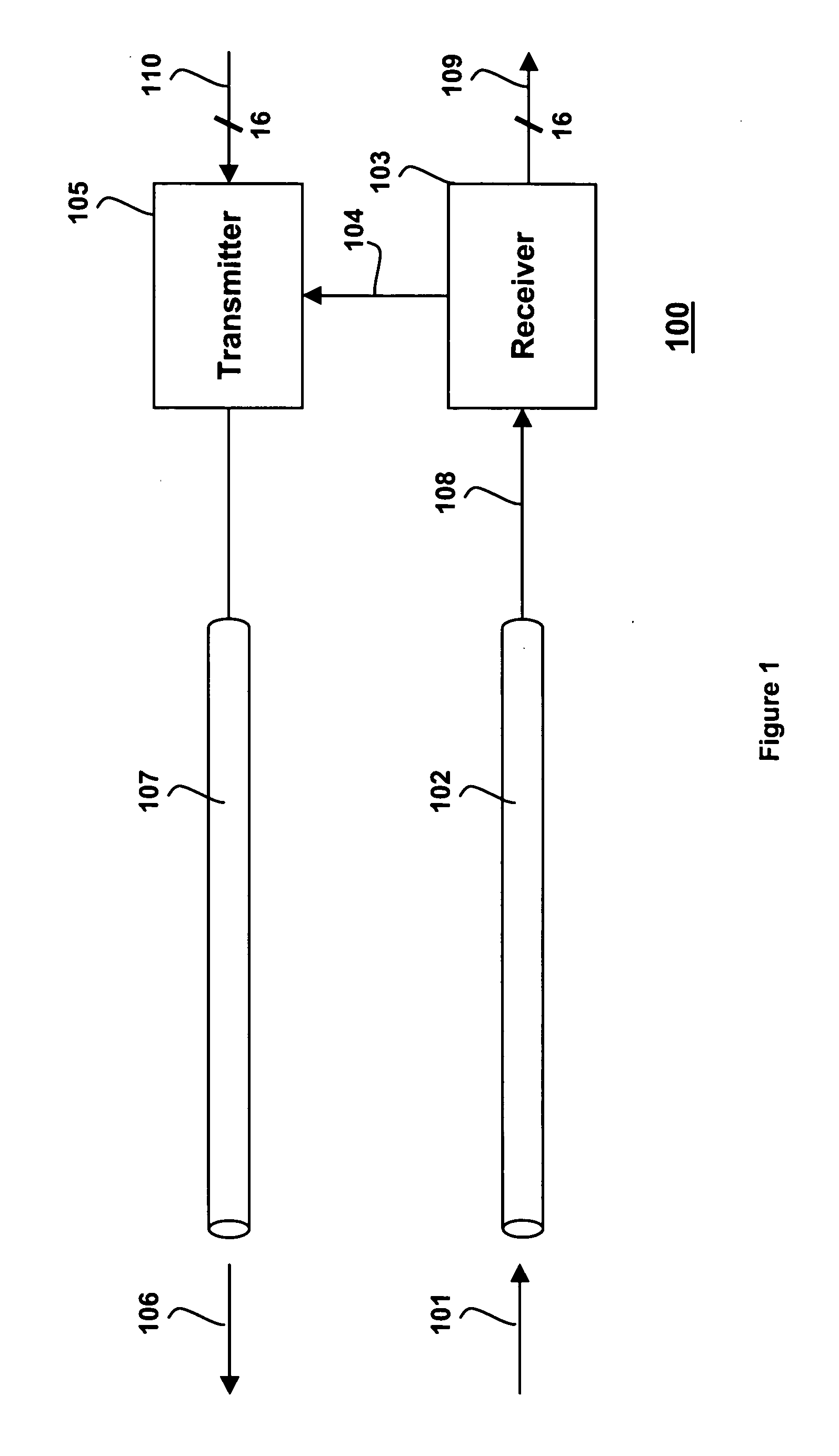
[0020]Transceiver circuitry must have the capability to test bi-directional communication links to which they are connected. FIG. 1 illustrates the concept of a line loop back test addressed by the present invention. In some applications, there are separate integrated circuits that implement the receiver 103 and the transmitter 105, and also separate integrated circuits that perform the low speed upstream and downstream processing. In other applications, there is a single integrated circuit that acts as a transceiver and another single integrated circuit that receives and transmits lower speed parallel data. Other combinations are also possible. Ultimately, all of the high speed transceiver circuitry and lower speed parallel circuitry can be implemented on a single chip. Therefore, the separation of the various components can be arbitrarily partitioned. In the embodiment described herein, however, all of the circuitry required to implement the present invention is placed on the same...


PUM


Abstract

Method and circuitry for performing a line loop back test includes a receiver, a deserializer, and a low speed parallel loop back data multiplexer selects either the low speed parallel data from the deserializer when in loop back mode or low speed parallel input data when in normal mode. The deserializer produces a low speed clock output signal that is fed to a low speed loop back reference clock multiplexer and also to a low speed loop back clock multiplexer. Both the loop back reference clock multiplexer and the loop back clock multiplexer select the low speed clock output signal from the deserializer when in line loop back mode. A clock multiplying unit converts the output of the low speed loop back reference clock multiplexer into a high speed clock signal. The serializer generates the high speed serial transmitter data in synchronization with the high speed clock signal received from a clock multiplying unit. A clock divider circuit converts the high speed clock signal from the clock multiplying unit into a low speed FIFO output clock. A first-in-first-out buffer receives the low speed parallel output data in synchronization with a clock multiplexer output, and transmits low speed parallel FIFO data to the serializer in synchronization with the low speed FIFO output clock. A low speed parallel loop back data buffer provides coupling between the deserializer and the low speed parallel loop back data multiplexer, and a low speed loop back clock buffer provides coupling between the deserializer and the loop back reference clock multiplexer and the loop back clock multiplexer.

Description

BACKGROUND OF THE INVENTION[0001]1. Field of the Invention[0002]The present invention pertains to the field of high speed telecommunications transceivers; and specifically, to the field of testing high speed telecommunication links using the transceiver circuitry.[0003]2. Background of the Invention[0004]In many telecommunications applications, line loop-back mode is used to test the serial high-speed link between two locations. A stream of serial bits is sent over the link, fiber optics for example, to a receiver, which sends it directly to the transmitter and sends it back over the link to the original sender. The sender compares the transmitted and received data, and, if they match, the link must be functional. Such loop-back mode typically requires high speed multiplexers and buffers which are not only very difficult to implement, but also consume a great deal of power and degrade jitter performance of the normal mode operation.[0005]FIG. 1 illustrates general line loop back 100...

Claims


Application Information

Patent Timeline
Patent Type & Authority Patents(United States)
IPC IPC(8): H04J1/16H04L1/14H04L1/24
CPCH04L1/243
Inventor MOMTAZ, AFSHIN D.
Owner AVAGO TECH INT SALES PTE LTD
Why Eureka
Try Eureka