Reaction vessel and temperature control system

a technology of temperature control system and reaction vessel, which is applied in the direction of analytical using chemical indicators, instruments, glassware laboratories, etc., can solve the problems of long processing time, inefficiency of processes requiring precise temperature control, and affecting so as to achieve convenient and effective loading of samples, improve the quality of the reaction vessel, and improve the effect of temperature control

Inactive Publication Date: 2006-09-05
CEPHEID INC
View PDF37 Cites 48 Cited by
  • Summary
  • Abstract
  • Description
  • Claims
  • Application Information

AI Technical Summary

Benefits of technology

[0011]The present invention provides an improved instrument and reaction vessel for thermally controlling and optically interrogating a sample. In preferred aspects, the system of the present invention permits convenient and effective loading of a sample into the reaction vessel, rapid heating and cooling of the sample, optimal thermal transfer between the sample and heating or cooling elements, and real-time optical detection and monitoring of the sample with increased detection sensitivity.
[0020]In accordance with another aspect of the invention, a reaction vessel comprises a reaction chamber defined by two opposing major walls and side walls connecting the major walls to each other. At least one of the major walls comprises a sheet or film sufficiently flexible to conform to a heating or cooling surface. At least two of the side walls are optically transmissive to provide optical windows to the reaction chamber. The vessel also has a loading reservoir for receiving the sample prior to loading the sample into the reaction chamber. The loading reservoir is connected to the reaction chamber via a first channel. The vessel further includes an aspiration port for establishing a seal with an aspiration device. The aspiration port is connected to the reaction chamber via a second channel, thereby enabling the aspiration device to draw the sample from the loading reservoir into the chamber. The vessel also includes flow control means for preventing substantial flow of the sample from the loading reservoir into the reaction chamber until the sample is drawn into the reaction chamber by the aspiration device.
[0022]In accordance with another aspect of the invention, a reaction vessel comprises a reaction chamber and a loading reservoir for receiving the sample prior to loading the sample into the reaction chamber. The loading reservoir is connected to the reaction chamber via a first channel. The vessel also has an aspiration port for establishing a seal with an aspiration device, the aspiration port being connected to the reaction chamber via a second channel thereby enabling the aspiration device to draw the sample from the loading reservoir into the reaction chamber. The vessel further includes flow control means for preventing substantial flow of the sample from the loading reservoir into the reaction chamber until the sample is drawn into the reaction chamber by the aspiration device. The vessel also comprises first and second plugs for sealing the loading reservoir and the aspiration port, respectively, and for compressing gas in the vessel, thereby increasing pressure in the reaction chamber.
[0023]In accordance with another aspect of the invention, a reaction vessel comprises a reaction chamber and a loading reservoir for receiving the sample prior to loading the sample into the reaction chamber. The loading reservoir is connected to the reaction chamber via a first channel. The vessel also has an aspiration port for establishing a seal with an aspiration device, the aspiration port being connected to the reaction chamber via a second channel, thereby enabling the aspiration device to draw the sample from the loading reservoir into the reaction chamber. The vessel further includes flow control means for preventing substantial flow of the sample from the loading reservoir into the reaction chamber until the sample is drawn into the reaction chamber by the aspiration device. The vessel also has a seal aperture, extending over an outer end of the loading reservoir and an outer end of the aspiration port, for receiving a plug that is inserted into the aperture after loading the sample into the reaction chamber.

Problems solved by technology

First, due to the large thermal mass of a metal block, the heating and cooling rates in these instruments are limited, resulting in longer processing times. For example, in a typical PCR application, fifty cycles may require two or more hours to complete.
With these relatively slow heating and cooling rates, some processes requiring precise temperature control are inefficient.
For example, reactions may occur at the intermediate temperatures, creating unwanted and interfering side products, such as PCR “primer-dimers” or anomalous amplicons, which are detrimental to the analytical process.
Poor control of temperature also results in over-consumption of expensive reagents necessary for the intended reaction.

Method used


Image

  • Reaction vessel and temperature control system
  • Reaction vessel and temperature control system
  • Reaction vessel and temperature control system

Examples


Embodiment Construction

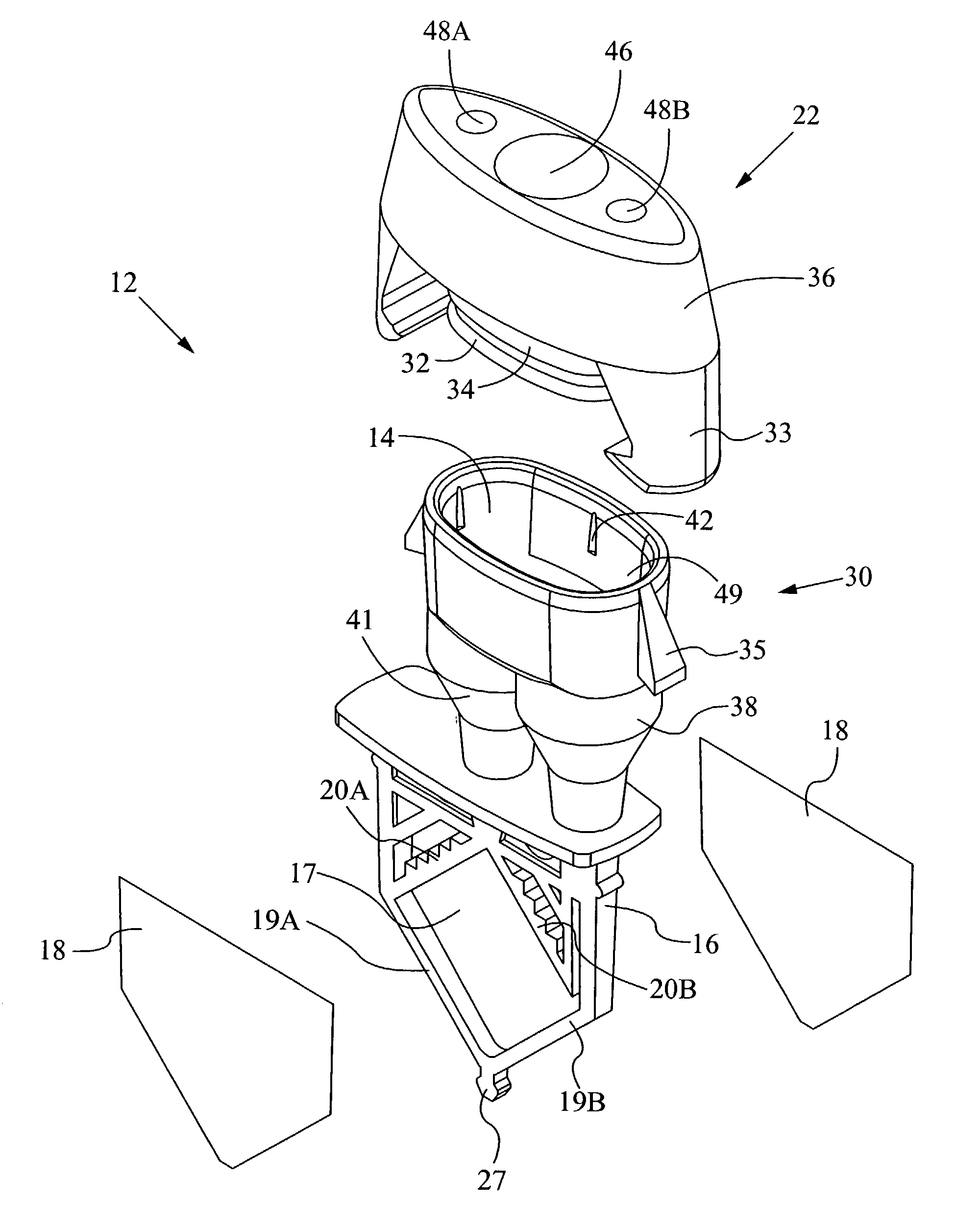
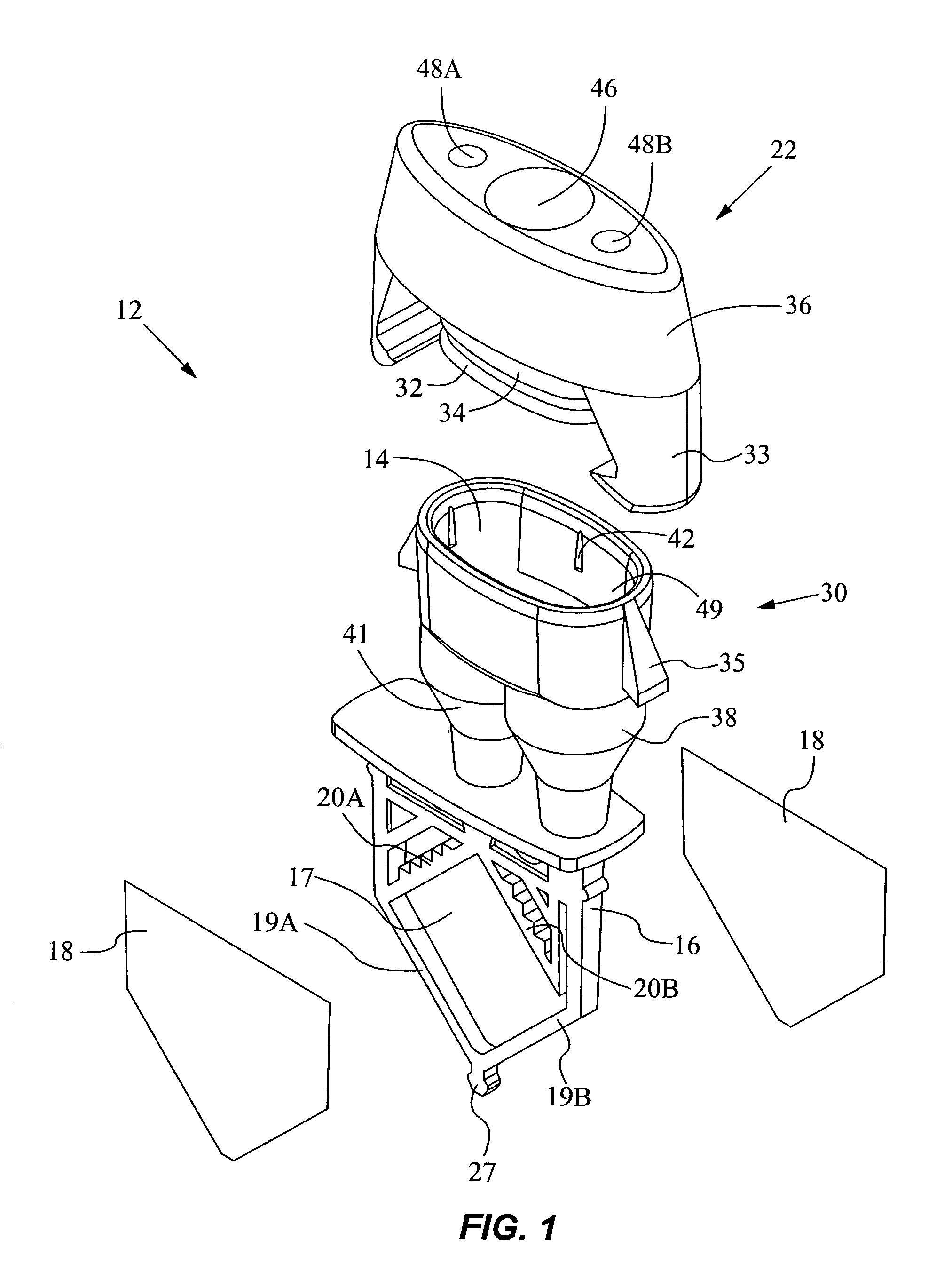
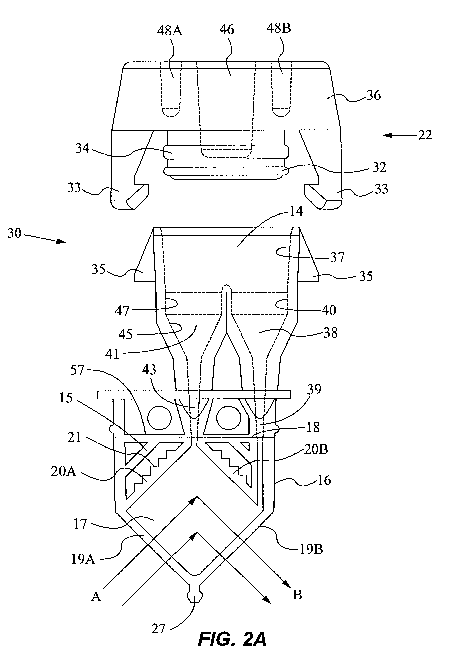
[0059]The present invention provides a reaction vessel and system for thermally controlling and optically interrogating a sample. The sample may be a solution or suspension containing particles, cells, microorganisms, ions, or small and large molecules, such as proteins and nucleic acids, etc. In a particular use, the sample may be a bodily fluid (e.g., blood, urine, saliva, sputum, seminal fluid, spinal fluid, mucus, or other bodily fluids). Alternatively, the sample may be a solid made soluble or suspended in a liquid or the sample may be an environmental sample such as ground or waste water, soil extracts, or pesticide residues. Further, the sample may be mixed with one or more chemicals, reagents, diluents, or buffers. The term “sample” is understood to encompass original samples of interest (e.g., bodily fluids), samples containing at least parts of original samples, and reaction products resulting from reactions of original samples.

[0060]In a preferred embodiment, the system i...


PUM

PropertyMeasurementUnit
thicknessaaaaaaaaaa
thicknessaaaaaaaaaa
pressureaaaaaaaaaa

Abstract

A reaction vessel has a reaction chamber, a loading reservoir connected to the reaction chamber via a first channel, and an aspiration port connected to the chamber via a second channel. To load the sample into the reaction chamber, the sample is dispensed into the loading reservoir and then drawn into the chamber by application of a vacuum to the aspiration port. A system for controlling the temperature of the sample in the reaction vessel includes one or more thermal elements for heating or cooling the sample and optionally optics for detecting one or more analytes in the sample.

Description

CROSS-REFERENCES TO RELATED APPLICATIONS[0001]This application is a continuation-in-part of commonly assigned, U.S. patent application Ser. No. 09 / 497,848, entitled “Reaction Vessel and Temperature Control System,” filed Feb. 4, 2000, now U.S. Pat. No. 6,403,037, the entire disclosure of which is incorporated herein by reference.FIELD OF THE INVENTION[0002]This invention relates to a reaction vessel and temperature control system.BACKGROUND OF THE INVENTION[0003]There are many applications in the field of chemical processing in which it is desirable to precisely control the temperature of a sample, to induce rapid temperature changes in the sample, and to detect target analytes in the sample. Applications for such heat-exchanging chemical reactions may encompass organic, inorganic, biochemical or molecular reactions. Examples of thermal chemical reactions include isothermal nucleic acid amplification, thermal cycling nucleic acid amplification, such as the polymerase chain reaction ...

Claims


Application Information

Patent Timeline
Patent Type & Authority Patents(United States)
IPC IPC(8): G01N15/06B01L3/02G01N1/10G01N21/00G01N21/03B01L3/00B01L3/14B01L7/00G01N35/04
CPCB01L3/502B01L7/52B01L3/50825B01L2200/026B01L2200/0642Y10T436/2575B01L2300/0654B01L2300/14B01L2400/049B01L2400/0644G01N2035/0405B01L2200/0684
Inventor CHANG, RONALDDORITY, DOUGLAS B.CHRISTEL, LEE A.PETERSEN, KURT E.
Owner CEPHEID INC
Why Eureka
Try Eureka