Lithographic apparatus comprising a gas flushing system

a technology of lithographic projection and flushing system, which is applied in the direction of electrical apparatus, printers, instruments, etc., can solve the problems of excessive operating costs, unacceptable intensity loss, and gas introduced inside the hood may leak to the outside, so as to reduce water and reduce transmission loss

Inactive Publication Date: 2006-09-12
ASML NETHERLANDS BV
View PDF8 Cites 17 Cited by
  • Summary
  • Abstract
  • Description
  • Claims
  • Application Information

AI Technical Summary

Benefits of technology

[0016]Hence, it is an aspect of the present invention to provide a system that reduces absorption of the projection beam light by water, e.g. on the resist. Another aspect of the invention is to remove part of the water from the resist before the projection beam reaches the surface of the resist on the substrate, and therefore to increase the transmission of the resist.
[0024]The radial gas flow dries or removes part of the water adsorbed on and present in the resist, before the projection beam reaches the resist. This advantageously reduces absorption of the projection beam light by water. In this way, the transmission loss is minimized, and the differences in transmission are also minimized. The atmosphere between the last lens of the projection system and the substrate, and between the gas flushing system and substrate, may now be better controlled. In an embodiment of the present invention, the radial gas flow, at least in the direction of movement of the substrate table (or support stable), has a velocity equal or higher than the instantaneous velocity of the substrate table (or substrate table).
[0025]In an embodiment of the present invention, the gas flushing system further comprises outlets (or outlet ports) and inlets (or inlet ports) that are constructed and arranged to generate a substantially laminar gas flow across at least part of said projection beam between a last lens of the projection system and said substrate. In this way, when using such a lithographic apparatus, absorption of the projection beam is minimized while avoiding detrimental effects on the throughput and maintenance overhead of the apparatus, as well as reducing the use of expensive consumables. The laminar flow across the last lens of the projection system also decreases the possibility of deposition of organic compounds on the surface of the last lens, e.g. from the resist.
[0027]According to a further embodiment of the present invention, the gas flushing system further includes extra exhaust inlets (or radial gas flow exhaust inlets) which are located to the outside, with respect to the outlets (or radial gas flow outlets), of said gas flushing system which provide the radial gas flow, and which are arranged to exhaust part or a substantial part of the gas radial gas flow, which is directed outwards in said space. This also leads to a better-controlled atmosphere outside of the region between the last lens of the projection system and the substrate and thus to a better controlled transmissions and indices of refraction. This is advantageous, since, e.g., sensors that determine the height of the substrate or the position can be very sensitive to slight differences in transmission and / or indices of refraction.
[0034]Hence, this invention provides a method and apparatus to reduce water on and in the resist, before the resist is exposed to the radiation, and also a method to reduce the transmission losses as a result of water present in and on the resist.

Problems solved by technology

However, such wavelengths are strongly absorbed by normal atmospheric air leading to unacceptable loss of intensity as the beam traverses the apparatus.
To enclose the entire apparatus and operate in vacuum would introduce unacceptable delays in wafer and reticle exchange, whereas to flush the entire apparatus with a gas which does not absorb the illumination wavelength, such as ultra-pure nitrogen (N2), would result in excessive operating costs due to the consumption of the gas in an imperfectly closed machine.
Furthermore, the gas introduced inside the hood may leak to the outside and change the gas composition outside the hood.
Sensors, e.g., for determining the position or height of the wafer, etc, for example based on transmission or index of refraction of the gas, may in this way be disturbed, which will lead to less reproducible results.
In addition, photo-resist polymers are known to take up rather large amounts of water (several vol.
The amount of water remaining during illumination may well lead to a much larger transmission loss than that caused by water in the vapour phase.

Method used


Image

  • Lithographic apparatus comprising a gas flushing system
  • Lithographic apparatus comprising a gas flushing system
  • Lithographic apparatus comprising a gas flushing system

Examples


Embodiment Construction

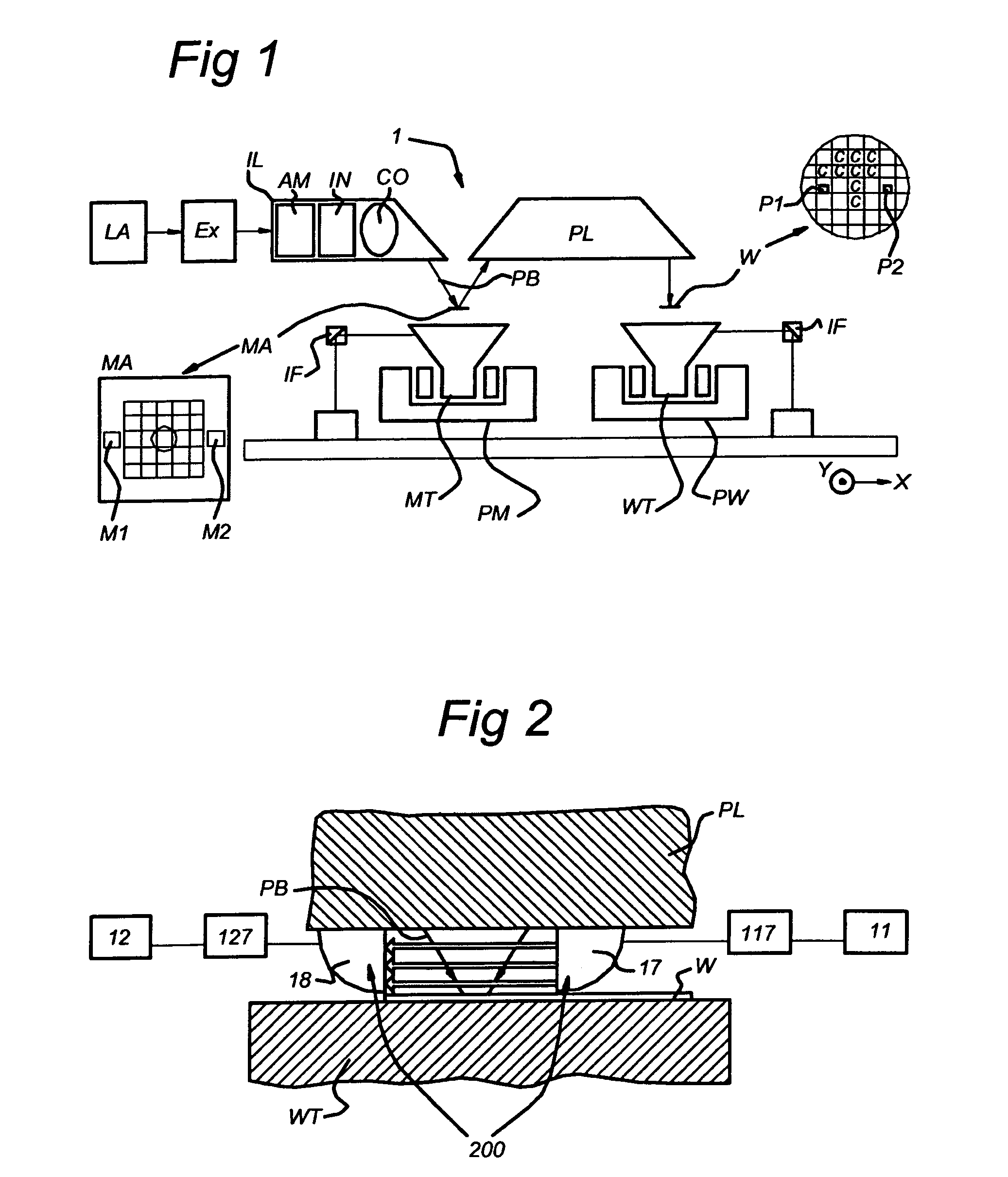
[0060]FIG. 1 schematically depicts a lithographic projection apparatus 1 according to a particular embodiment of the invention. The apparatus includes:[0061]a radiation system including a radiation source LA, a beam expander Ex, and an illumination system IL, configured to supply a projection beam PB of radiation (e.g. 157 nm radiation);[0062]a first object table (mask table) MT provided with a mask holder and configured to hold a mask MA (e.g. a reticle), and connected to first positioning device PM that is configured to accurately position the mask with respect to item PL;[0063]a second object table (substrate table or substrate support) WT provided with a substrate holder and configured to hold a substrate W (e.g. a resist-coated silicon wafer), and connected to second positioning device PW that is configured to accurately position the substrate with respect to item PL; and[0064]a projection system (“lens”) PL (e.g. refractive, catadioptric or reflective optics) constructed and a...


PUM

PropertyMeasurementUnit
lengthaaaaaaaaaa
lengthaaaaaaaaaa
lengthaaaaaaaaaa

Abstract

A lithographic projection apparatus includes a radiation system constructed and arranged to supply a projection beam of radiation, a support structure constructed and arranged to support a patterning structure, the patterning structure constructed and arranged to pattern the projection beam according to a desired pattern, a substrate support constructed and arranged to support a substrate, and a projection system constructed and arranged to project the patterned beam onto a target portion of the substrate. The apparatus further includes a gas flushing system comprising radial gas flow outlets, said gas flushing system being constructed and arranged to generate a radial gas flow through said radial gas flow outlets in an intermediate space defined between said gas flushing system and said substrate, wherein the radial gas flow has a radial velocity directed outwards in said space with a magnitude larger than zero at every location in said space.

Description

[0001]This application claims priority from European Patent Application No. 03075416.2, filed Feb. 12, 2003, herein incorporated by reference in its entirety.BACKGROUND OF THE INVENTION[0002]1. Field of the Invention[0003]This invention relates to a lithographic projection apparatus and more particularly to a lithographic projection apparatus including a gas flushing system.[0004]2. Description of Related Art[0005]The term “patterning structure” used herein should be broadly interpreted as referring to structure that can be used to endow an incoming radiation beam with a patterned cross-section, corresponding to a pattern that is to be created in a target portion of the substrate; the term “light valve” can also be used in this context. Generally, the said pattern will correspond to a particular functional layer in a device being created in the target portion, such as an integrated circuit or other device (see below). Examples of such patterning structure include:[0006]A mask. The c...

Claims


Application Information

Patent Timeline
Patent Type & Authority Patents(United States)
IPC IPC(8): G03B27/52G03B27/42G03F7/20H01L21/027
CPCG03F7/70933G03F7/20
Inventor DE BOKX, PIETER KLAASVAN EMPEL, TJARKO ADRIAAN RUDOLFHULTERMANS, RONALD JOHANNESJONKERS, ADRIANUS CORNELIUS ANTONIUS
Owner ASML NETHERLANDS BV
Why Eureka
Try Eureka