
Servo systems, servo heads, servo patterns for data storage especially for reading, writing, and recording in magnetic recording tape

Inactive Publication Date: 2006-09-12
ADVANCED RES
View PDF45 Cites 70 Cited by
  • Summary
  • Abstract
  • Description
  • Claims
  • Application Information

AI Technical Summary

Benefits of technology

[0023]The present invention provides improved methods and systems for data recording and reading for increasing overall tape data storage density, especially for data written in azimuth style. The principles of the invention provide servo formats and systems that allow accurate on track guidance for higher density applications and that are less sensitive to off track error. Preferred embodiments of the invention offer servo formats and systems of the invention that allows positive track and group identification at the beginning, end, and optionally periodically along the length of a tape.
[0026]Third, and counter-intuitively, the servo track pitch, centertap width, and / or centertap sensor widths may be increased relative to conventional practice to improve data density. For instance, the centertap width may be arbitrarily wide so as to allow the two sensors of a centertapped servo head to detect signals from two nonadjacent servo tracks. With this approach, the data tracks can have a pitch that is a fraction of the servo track pitch, helping to facilitate high density data recording, playback, and erasing. Additionally, a higher quality servo signal is obtained by using relatively large servo track pitches and servo sensors. This aspect of the invention is particularly preferred in data storage systems whose media incorporate servo tracks written at the same or different azimuth angles.

Problems solved by technology

Thus, the read head element also (as is also limited by read head performance characteristics) limits how narrow the data track can be, and hence the maximum track density.
Not only is the data track width limited by the minimum read element size in order to meet the recording system's performance criterion, it also is limited to accommodate expected misregistration as may occur under the dynamic conditions of moving media and as may be determined empirically or by modeling.
If a read head moves off the data track for whatever reason and begins to read a signal from the adjacent track, the possibility of erroneous data transfer increases.
More specifically, the error rate is known to increase exponentially as the read head moves further off the data track.
Reading narrow is unfortunately limited by making an acceptable read element that will still meet signal amplitude, SNR (signal to noise ratio), and media defect sensitivity requirements.
There are a number of potential sources of read element to written track misregistration error, which error is systematic in that both the media and the drive are involved as potential sources of error.
The principal sources of error include tape lateral motion, vibration in the head / actuator assembly, dimensional instability of the media substrate, and mechanical misalignments between read and write elements in manufacturing and assembly.
Probably the most significant limitation on tape track densities is the tendency for the tape to experience lateral tape motion, which is a tendency for the tape to shift laterally relative to the linear direction of tape motion.
During reading, lateral tape motion can cause misregistration of the read head over the track being read.
This build-up of potential misregistration of data tracks combined with other less significant potential sources of misregistration can result in a portion of the read element to be positioned over an adjacent data track, which, if significant enough, can cause an unacceptable level of data transfer errors.
However, as noted above, limitations of minimum signal amplitude, signal-to-noise-ratio, and sensitivity to media defects provides a lower limit as to how narrow the read element can actually be.
As such, the effective read element size limits how narrow a data track can be made.
This provision of additional leads adds stiffness to the system that can inhibit or interfere with its motion capabilities.
The weaknesses of the AM approach include the susceptibility of the PES to dropouts and noise, the reduced sample rate, the wider band width to accommodate the modulation, and without writing (erasing the holes) the tracks individually, the inability to identify the selected track.
However, because of the narrowness of the servo transducer, the signal to noise ratio (SNR) is quite low.
Further, although the measurement is insensitive to any static variation in the tape speed, significant error may tend to be introduced by any dynamic variation in the tape speed.
Like the AM system, this approach typically does not provide for unique identification of the data track.
Further, modeling and simulation have shown that the current time-based approaches may be limited to intrinsic (to the servo pattern and head only) misregistrations of several tenths of micron, thus limiting maximum track density to 4,000–6,000 tracks per inch.

Method used


Image

  • Servo systems, servo heads, servo patterns for data storage especially for reading, writing, and recording in magnetic recording tape
  • Servo systems, servo heads, servo patterns for data storage especially for reading, writing, and recording in magnetic recording tape
  • Servo systems, servo heads, servo patterns for data storage especially for reading, writing, and recording in magnetic recording tape

Examples


Embodiment Construction

[0138]The embodiments of the present invention described below are not intended to be exhaustive or to limit the invention to the precise forms disclosed in the following detailed description. Rather a purpose of the embodiments chosen and described is so that the appreciation and understanding by others skilled in the art of the principles and practices of the present invention can be facilitated.

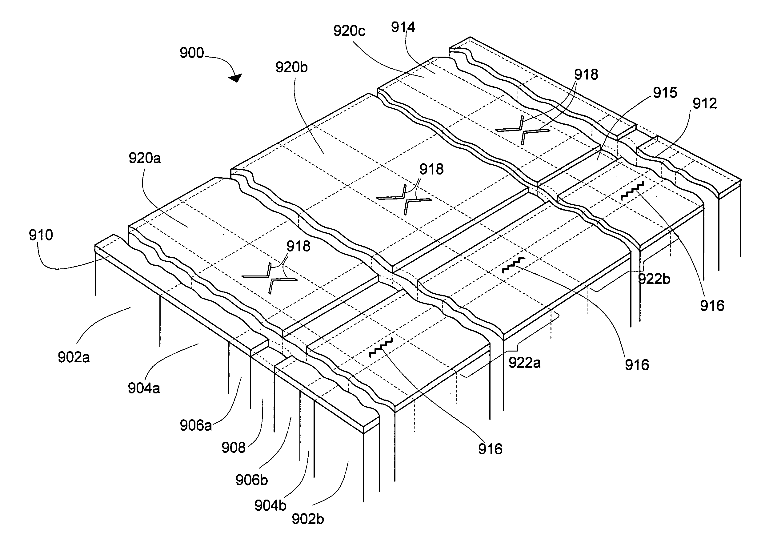
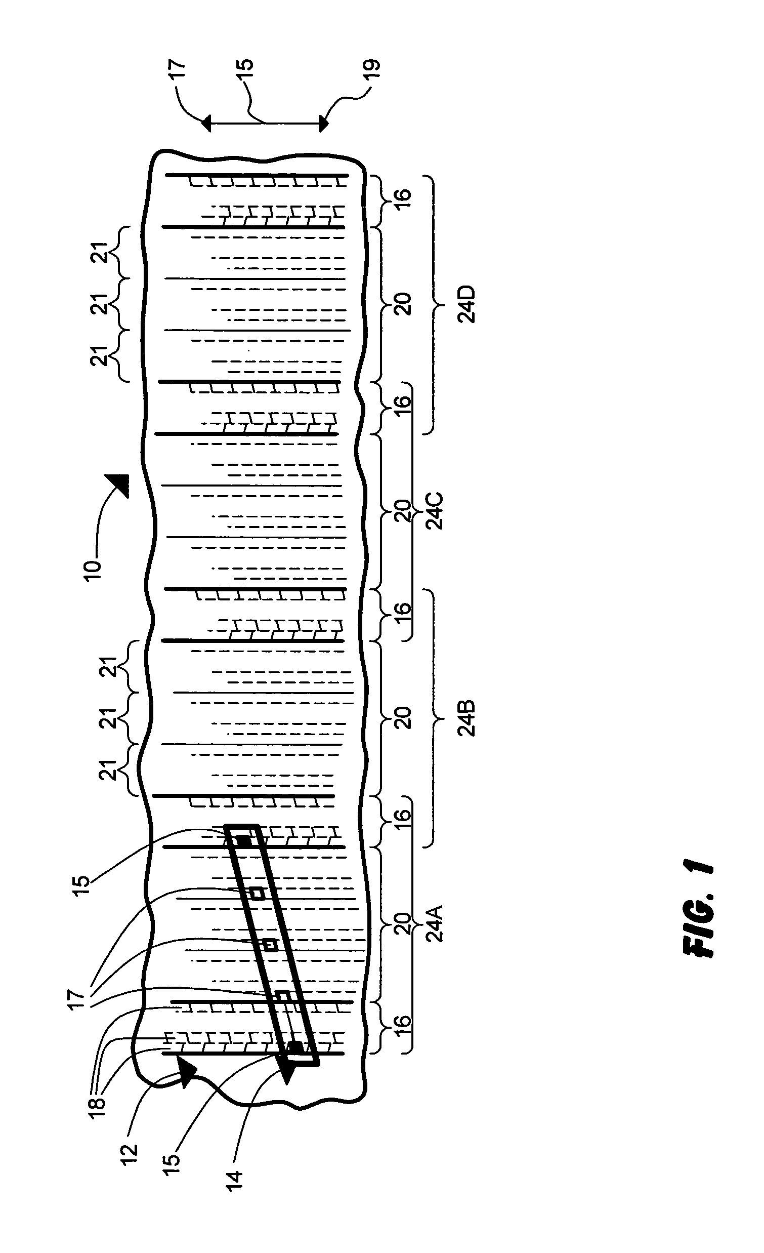
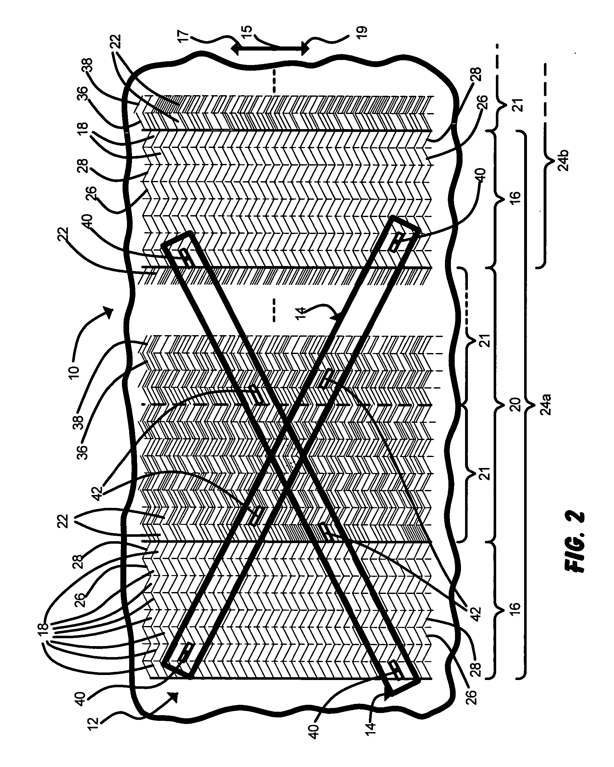
[0139]FIGS. 1, 2, and 3 schematically show one embodiment of a data storage system 10 of the present invention that combines azimuth servo features, azimuth data features, and servo and data transducers that are generally co-linear and / or are parallel to the corresponding azimuthal transitions of the servo and data bands during reading, writing, and erasing operations. System 10 is in the exemplary form including a magnetic recording tape 12 (a portion of the length being shown) that is readingly, writingly, and erasingly coupled to read / write head 14.

[0140]Tape 12 includes one or more ser...


PUM

PropertyMeasurementUnit
Lengthaaaaaaaaaa
Timeaaaaaaaaaa
Electrical conductivityaaaaaaaaaa

Abstract

Methods and systems for data recording and reading for increasing overall tape data storage density, especially for data written in azimuth style. The principles of the invention provide servo formats and systems that allow accurate on track guidance for higher density applications and that are less sensitive to off track error. Preferred embodiments of the invention offer servo formats and systems of the invention that allows positive track and group identification at the beginning, end, and optionally periodically along the length of a tape.

Description

PRIORITY CLAIM[0001]The present non-provisional Application claims priority under 35 USC §119(e) from U.S. Provisional Patent Application having Ser. No. 60 / 469,519, filed on May 9, 2003, by Dugas et al. and titled SERVO FORMAT FOR AZIMUTH RECORDING; U.S. Provisional Patent Application having Ser. No. 60 / 509,031, filed on Oct. 6, 2003, by Dugas et al. and titled SERVO FORMAT FOR AZIMUTH RECORDING; and U.S. Provisional Patent Application having Ser. No. 60 / 469,517, filed on May 9, 2003, by Dugas et al. and titled SERVO BAND WITH ZIGZAG TRANSITIONS FOR AZIMUTH RECORDING IN LINEAR TAPE; wherein each of these provisional Applications is commonly owned by the assignee of the present application and wherein the entire contents of each is incorporated herein by reference.FIELD OF THE INVENTION[0002]The present invention relates generally to data storage reading, writing, and erasing systems, techniques, and devices incorporating servo capabilities and features. In particular, the present i...

Claims


Application Information

Patent Timeline
IPC IPC(8): G11B21/02G11B5/008G11B5/29G11B5/584
CPCG11B5/00813G11B5/29G11B5/584Y10T29/49128Y10T29/49032Y10T29/49048Y10T29/49046Y10T29/4906Y10T29/49052Y10T29/49043Y10T29/49044
Inventor DUGAS, MATTHEW P.SCHWARZ, THEODORE A.WAGNER, GREGORY L.
Owner ADVANCED RES
Learn More