Switching-bursting method and apparatus for reducing standby power and improving load regulation in a DC-DC converter

a technology of dc-dc converters and switch-bursting, which is applied in the direction of electric variable regulation, process and machine control, instruments, etc., can solve the problems of significant load on the public electricity supply significant power loss at no-load, and poor output voltage regulation of low power converters designed for open-loop operation. achieve the effect of improving no-load to full-load output voltage regulation, shortening the duty cycle, and prolonging the turn-off tim

Inactive Publication Date: 2006-09-12
ASTEC INT LTD
View PDF10 Cites 36 Cited by
  • Summary
  • Abstract
  • Description
  • Claims
  • Application Information

AI Technical Summary

Benefits of technology

[0014]Another advantage of the present invention is that it provides improved no-load to full-load output voltage regulation using an open feedback loop system by maintaining a shorter duty cycle, with longer turn-off time at no-load, while maintaining the output voltage swing closer to the full-load level. The reduced duty cycle provided by the present invention prevents the output voltage from swinging high with respect to the full-load level, thereby providing good no-load and full-load output regulation even in open feedback loop systems.
[0015]Still another advantage of the present invention is that it provides for a very low no-load switching frequency and duty cycle by increasing the turn off time of the main switch through use of a turn off transistor driven by a zener diode, thereby maintaining conduction even with a very small base current and prolonging the off time of the main switch.
[0016]Yet another advantage of the present invention is that it provides the above advantages through the use of simpler, low cost discrete components, instead of more costly integrated circuits.
[0017]Broadly stated, the present invention provides a method of providing no-load to full-load regulation and reducing the power consumption under low-load or no-load conditions of a power converter in an open feedback loop system using a first switch to control current flow through the primary winding of a transformer, comprising the steps of: providing an output to a secondary winding of the transformer through self-oscillation; increasing the turn off time of the first switch at no-load via a second switch driven by a zener diode; maintaining the zener diode in conduction via a first capacitor charged by an auxiliary winding of the transformer; and maintaining conduction of the second switch using a very small control current so as to prolong the off time of the first switch such that a reduced duty cycle with longer off time of the first switch is maintained at no-load and to substantially reduce the difference between the output voltage under low-load or no-load and the corresponding output voltage under a full-load condition.
[0018]Broadly stated, the present invention also provides a DC-DC converter having first and second input terminals to which an input DC voltage is coupled and two output terminals where the output DC power is provided, comprising a transformer comprising a primary winding, a secondary winding, and an auxiliary winding, each winding having a first and second end, the secondary winding coupled to the output terminals; a first switch for controlling current flow through the primary winding, the first switch having a control input and one end connected to the primary winding and the other end coupled to the second input terminal, wherein an output to the secondary winding is provided through self-oscillation and wherein the auxiliary winding is coupled between the second input terminal and the control input; a first capacitor charged by the auxiliary winding during the off time of the first switch until the energy of the transformer is depleted; a control circuit comprising a second switch connected between the control input of the first switch and the other end of the first switch, the second switch having a control input; and a second capacitor connected between the control input of the first switch and the control input of the second switch; and a zener diode connected in series with the first capacitor between the second input terminal and the control input of the second switch; wherein the first capacitor is charged by the auxiliary winding so as to maintain the zener diode in conduction causing the second switch to maintain a conduction state so as to extend the turn off time of the first switch during a low load or no-load condition.

Problems solved by technology

The “standby” power consumption, e.g., when the equipment is off and the batteries are fully charged, of low power converters places a significant load on the public electricity supply.
Conventional low power converters designed for open-loop operation typically exhibit poor output voltage regulation and significantly high power losses at no-load.
As the switching frequency for the main switch is increased, however, the switching loss for the power converter also increases.
As a result, there is an undesirably high no-load standby power consumption for the conventional power converter.
Thus, in addition to the substantial power consumption at standby or no-load, power converter 10 exhibits poor voltage regulation.

Method used


Image

  • Switching-bursting method and apparatus for reducing standby power and improving load regulation in a DC-DC converter
  • Switching-bursting method and apparatus for reducing standby power and improving load regulation in a DC-DC converter
  • Switching-bursting method and apparatus for reducing standby power and improving load regulation in a DC-DC converter

Examples


Embodiment Construction

[0027]The present invention overcomes the drawbacks of the known RCC circuits and their methods of operation by significantly reducing no-load and standby power consumption and improving no-load to full-load regulation. In a preferred embodiment, the reduction in power consumption and the improved load regulation are achieved through the use of basic, discrete components in the converter circuit. The present invention provides improved output load regulation in open-loop operation. Alternatively, the circuit and method of the present invention may be utilized in closed-loop systems that otherwise exhibit undesirable power consumption at no-load and standby power conditions.

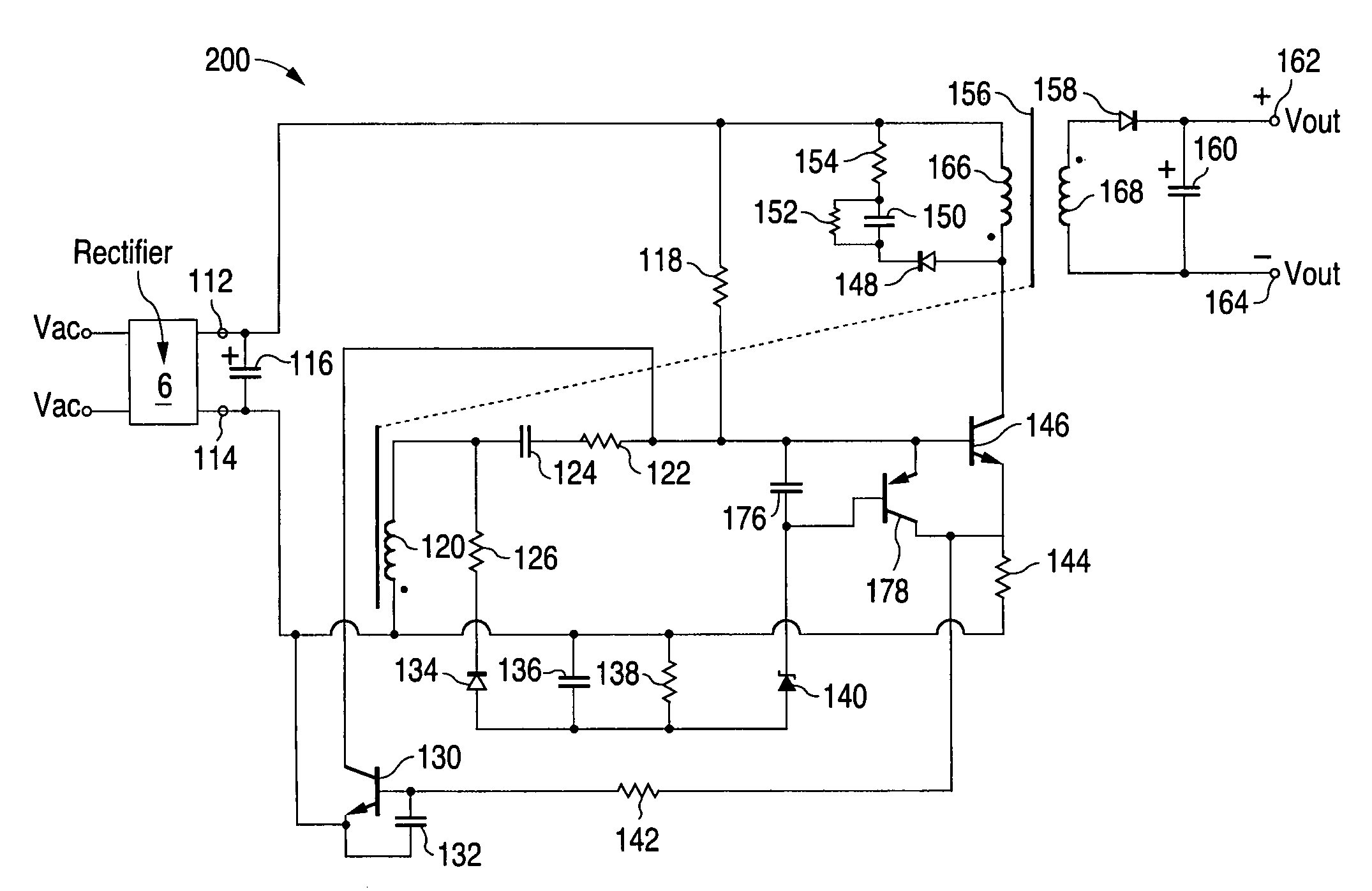
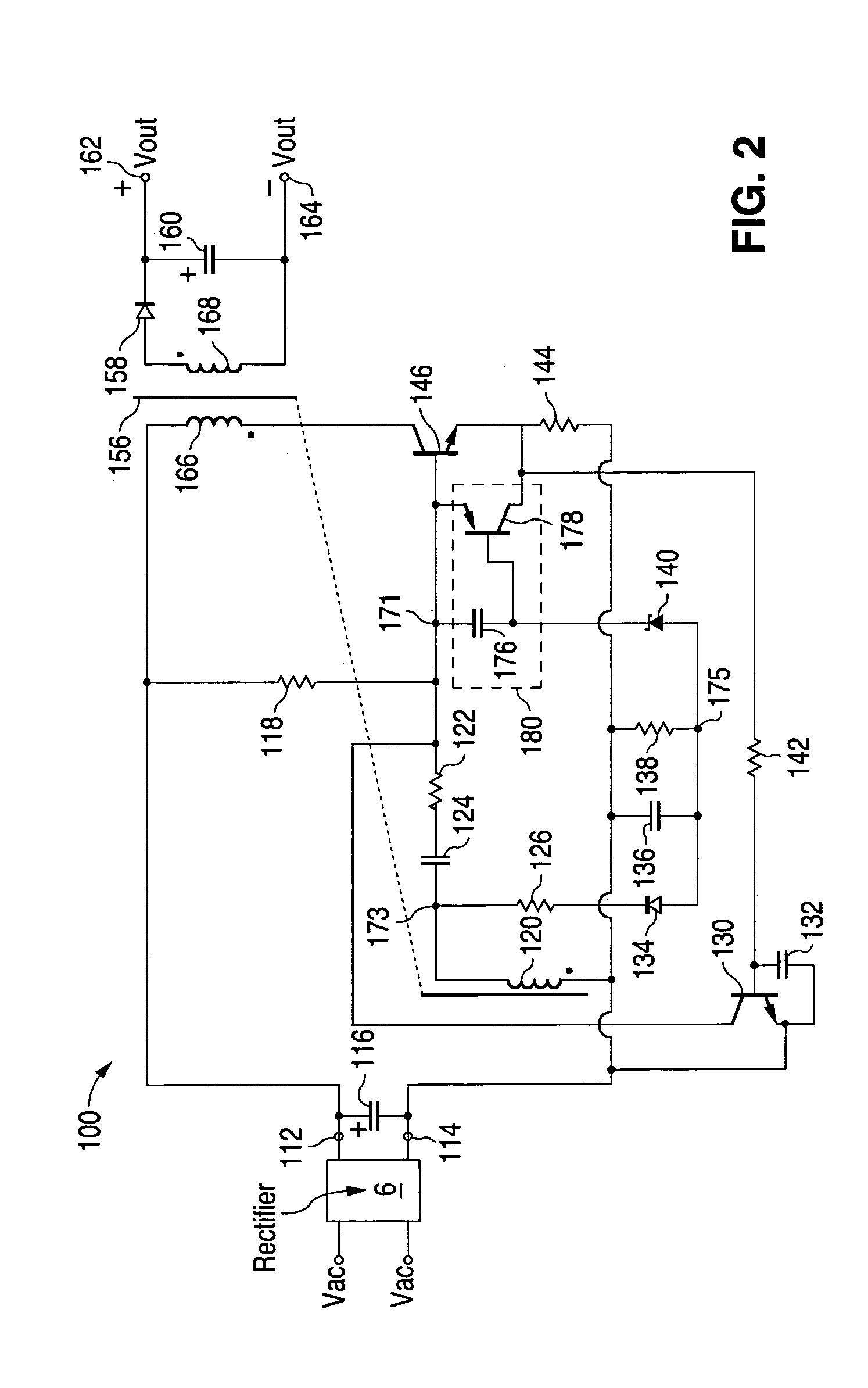
[0028]The present invention is illustrated with reference to FIGS. 2–7. FIG. 2 is a schematic diagram of a preferred embodiment of the circuit and corresponding method according to the present invention. For converter 100 in FIG. 2, an input AC voltage from an external AC source (not shown) is preferably transform...


PUM


Abstract

A circuit and corresponding method for reducing standby power and improving no-load to full-load regulation for ringing choke converters by maintaining a reduced duty cycle, with longer off time at no-load, while maintaining the output voltage swing closer to the full-load level. This reduced duty cycle prevents the output voltage from swinging high with respect to the full-load level, thereby providing good no-load and full-load output regulation in open feedback loop systems. The circuit and method provides very low no-load switching frequency and duty cycle by increasing the off time of the main switch through use of a turn off transistor driven by a zener diode, thereby maintaining conduction even with a very small control current and prolonging the off time of the main switch. The circuit and method achieves the benefits preferably using only less costly basic discrete converter components instead of more costly integrated circuits.

Description

CROSS REFERENCE TO RELATED APPLICATION[0001]This application claims the benefit of U.S. Provisional Application No. 60 / 491,176, filed Jul. 29, 2003, which is incorporated by reference herein.FIELD OF INVENTION[0002]The present invention relates to power converters, and more particularly, to a circuit and corresponding method for reducing standby power and improving no-load to full-load regulation for a DC-DC converter.BACKGROUND OF THE INVENTION[0003]Many electronic devices utilizing low power converters typically have no on / off switch and are frequently left permanently “plugged-in” to a wall socket. The “standby” power consumption, e.g., when the equipment is off and the batteries are fully charged, of low power converters places a significant load on the public electricity supply. Such concerns have prompted the European Commission Code of Conduct on Efficiency of External Power Supplies, for example, to commit signatories thereto to achieve a no-load power consumption maximum of...

Claims


Application Information

Patent Timeline
Patent Type & Authority Patents(United States)
IPC IPC(8): H02M3/338H02M3/335H02P
CPCH02M3/3385Y02B70/16H02M2001/0032H02M1/0032Y02B70/10
Inventor MABANTA, SAMUEL P.REYES, DONNIFERPONCE, MIRASOL
Owner ASTEC INT LTD
Why Eureka
Try Eureka