Condenser microphone

a condenser microphone and microphone body technology, applied in the direction of electrical transducers, transducer types, electric/electrostrictive transducers, etc., can solve the problems of limited vibration plate area, limited securing difficult to keep the property if miniaturized, etc., to achieve enlargement of vibration plate area, increase of housing density, and downsizing of the body

Inactive Publication Date: 2006-09-12
SONY CORP
View PDF2 Cites 16 Cited by
  • Summary
  • Abstract
  • Description
  • Claims
  • Application Information

AI Technical Summary

Benefits of technology

[0020]In the condenser microphone, the plurality of vibration plates are formed into the squares shapes, and the body for accommodating those vibration plates is formed into the shape of substantially quadratic prism, which does not lead to the creation of useless accomm

Problems solved by technology

However, since the condenser microphone shown in FIG. 2 has only one vibration plate, there is a limitation on securing the vibration plate area.
Thus, as compared with the rectangular

Method used


Image

  • Condenser microphone
  • Condenser microphone
  • Condenser microphone

Examples


Embodiment Construction

[0035]The preferred embodiment of a condenser microphone according to the present invention will be described below in detail with reference to the drawings.

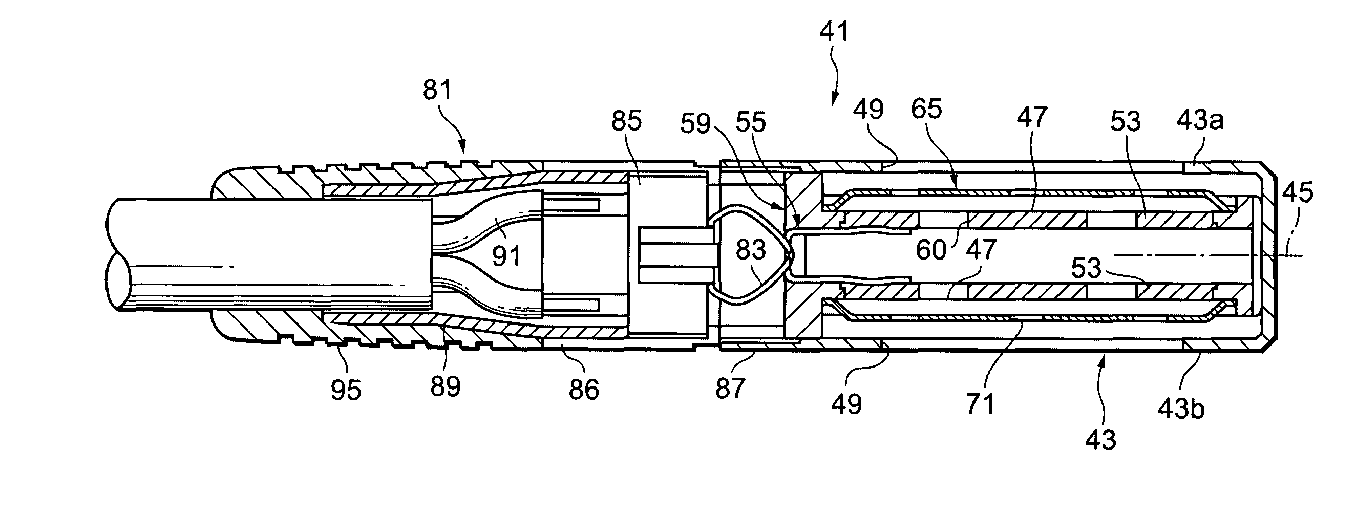
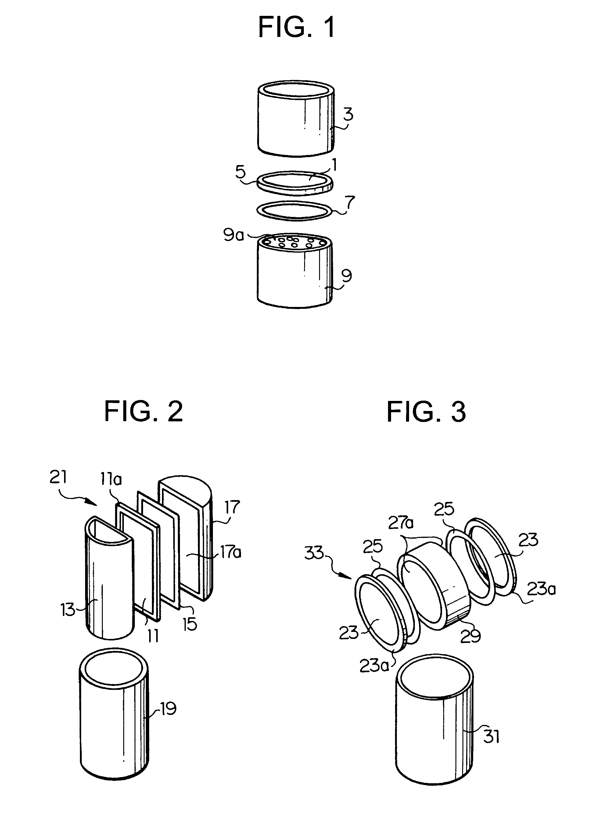
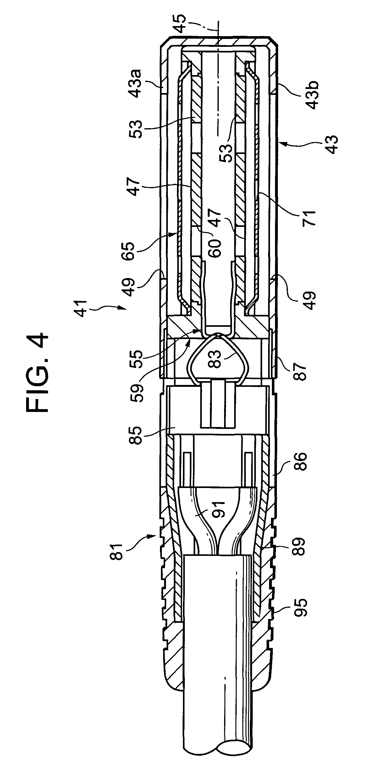
[0036]FIG. 4 is a sectional view showing a condenser microphone according to the present invention together with an adaptor. FIG. 5 is a detailed sectional view of the condenser microphone shown in FIG. 4. FIG. 6 is an A—A arrow direction view in FIG. 5. FIG. 7 is a sectional view of a back pole plate case shown in FIG. 5. FIG. 8 is a B—B arrow direction view in FIG. 7. FIG. 9 is a C—C arrow direction view in FIG. 8. FIG. 10 is a D—D arrow direction view in FIG. 8. FIG. 11 is a sectional view of a tray shown in FIG. 5. FIG. 12 is an E—E arrow direction view in FIG. 11. And, FIGS. 13A, 13B and 13C are explanatory views showing an example of a structure for preventing the back pole plate case and a back pole plate from being fallen-off.

[0037]For achieving downsizing of the condenser microphone, it is important to have a structure ...


PUM


Abstract

The present invention relates to a condenser microphone whose body can be miniaturized while keeping a property and a sound quality comparable to those of a conventional condenser microphone. The condenser microphone includes a cylindrical body, a plurality of vibration plates which are formed into the shapes of squares and placed in parallel to a body axis line within the body, acoustic holes formed on a body side wall in a direction vertical to the vibration plates and back pole plates which are placed on a side opposite to the acoustic holes with the vibration plate between and face on the respective vibration plates at an interval of a micro gap. A potential of the back pole plate is varied according to a vibration of the vibration plate.

Description

RELATED APPLICATION DATA[0001]This application claims priority to Japanese Patent Application JP 2002-196343 filed on Jul. 4, 2002, and the disclosure of that application is incorporated herein by reference to the extent permitted by law.BACKGROUND OF THE INVENTION[0002]1. Field of the Invention[0003]The present invention relates to a condenser microphone having vibration plates and back pole plates. More particularly, the present invention relates to a condenser microphone in which a miniaturization and a high sound quality are realized so as to be preferably used for the sound collection for the stocking in a musical, a drama or the like.[0004]2. Description of Related Art[0005]Higher sound quality and smaller size are required for condenser microphones used, for example, in the sound collection for stocking of the musical, the drama or the like. Most of those kinds of the condenser microphones usually employ a structure as shown in FIG. 1. That is, a vibration plate 1 is placed i...

Claims


Application Information

Patent Timeline
IPC IPC(8): H04R25/00H04R19/01H04R19/04
CPCH04R19/04
Inventor KANDA, HIROSHIOHYAMA, SHINJITOMIYAMA, YASUAKI
Owner SONY CORP
Why Eureka
Try Eureka