Radiation hard divider via single bit correction

Inactive Publication Date: 2006-09-12
THE BOEING CO
View PDF3 Cites 2 Cited by
  • Summary
  • Abstract
  • Description
  • Claims
  • Application Information

AI Technical Summary

Benefits of technology

[0009]The present invention permits the use of faster clock speeds, designs require that the clock period be long enough to allow data to propagate from the dividers, through the voting module, and back to the divider before the next clock edge occurs. Hence, data must be sent through the voter and fed back to the inputs of all the dividers within a single clock cycle. This limits the maximum clock frequency of the divider network. The present invention takes the voter out of the feedback loop. Instead, data is evaluated in parallel with the voting scheme, and corrupted bits are corrected at a later clock cycle. Because the data thus has fewer gates to propagate through, a faster clock signal can be used. The correction technique also corrects corrupted bits internal to the divider so that phase and frequency coherency between all dividers is re-established before the next SEU event.
[0010]The present invention does not require a “hard” voter module (one that is impervious to SEU events) to perform divider correction and maintain phase-frequency coherency. At higher clock frequencies, the wire-OR scheme of such “hard” voters introduce significant signal ringing and potentially fatal oscillation problems. Further, even “hard” voters can be susceptible to SEUs, and if the voter were somehow upset, corrupt data would be fed back to the dividers, possibly causing a functional failure. The present invention uses a “soft” voter that circumvents the ringing problem typically associated with hard voter designs. This is accomplished by identifying when the voter has been upset and deactivating certain signal paths to ensure that phase and frequency coherency are maintained.

Problems solved by technology

This results in a clock signal that does not move in discrete steps of 45 degrees or more in phase due to radiation caused upsets.
At higher clock frequencies, the wire-OR scheme of such “hard” voters introduce significant signal ringing and potentially fatal oscillation problems.
Further, even “hard” voters can be susceptible to SEUs, and if the voter were somehow upset, corrupt data would be fed back to the dividers, possibly causing a functional failure.

Method used


Image

  • Radiation hard divider via single bit correction
  • Radiation hard divider via single bit correction
  • Radiation hard divider via single bit correction

Examples


Embodiment Construction

[0020]In the following description, reference is made to the accompanying drawings which form a part hereof, and which is shown, by way of illustration, several embodiments of the present invention. It is understood that other embodiments may be utilized and structural changes may be made without departing from the scope of the present invention.

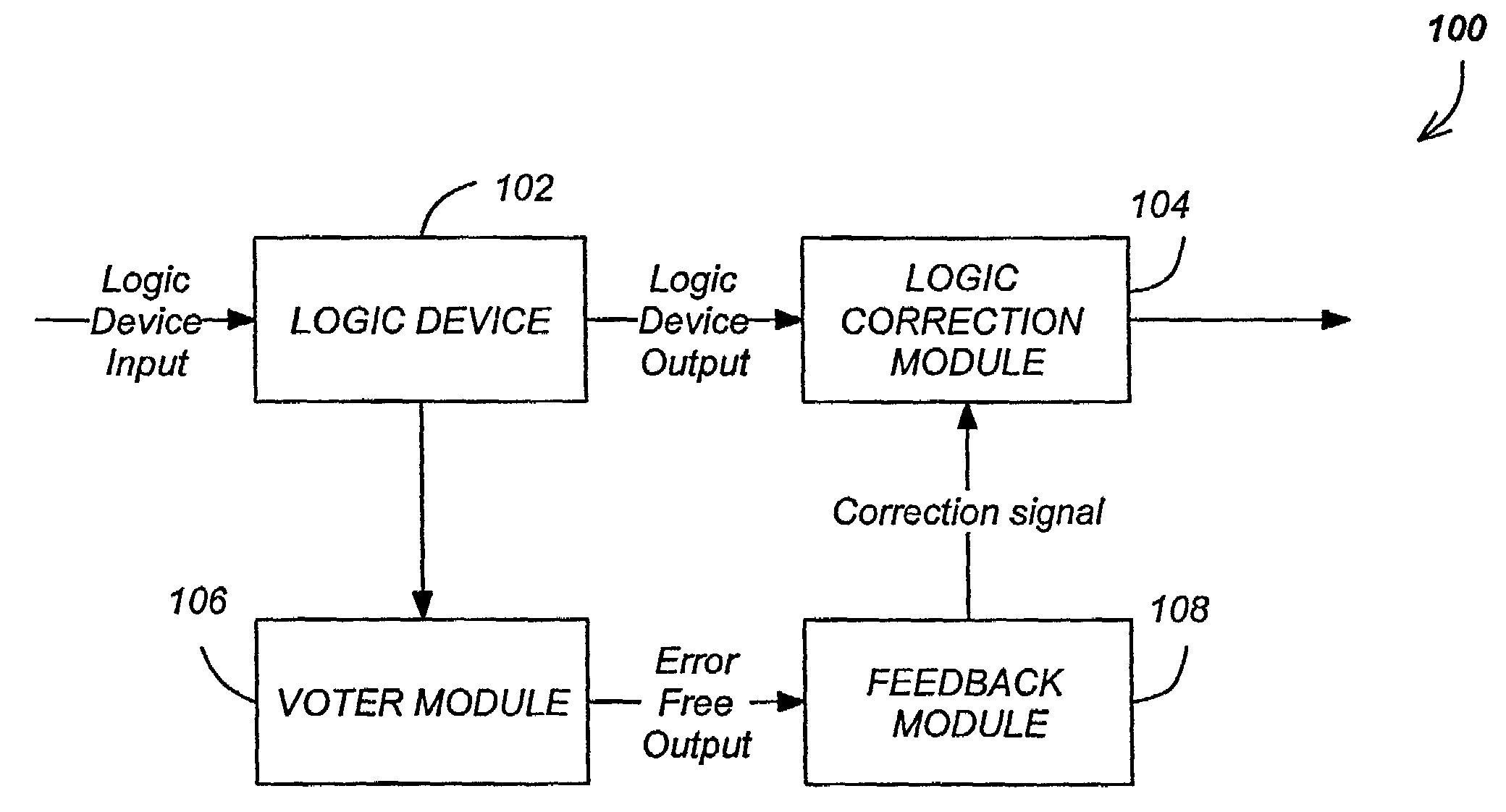
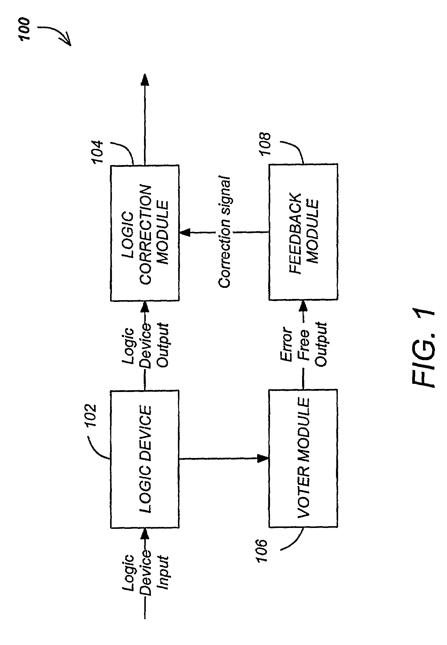
[0021]FIG. 1 is a diagram showing one embodiment of the present invention. A logic device 102 accepts a logic device input, and provides a logic device output. A logic correction module 104 accepts the logic device output, and in accordance with a correction signal from a feedback module 108, corrects the logic device 102 output to provide an error-free output. The feedback module generates the correction signal from an error free output signal from an error detection device such as a voter module 106. The logic device 102 could comprise any combination of discrete logic devices such as logic gates, flip-flops and inverters.

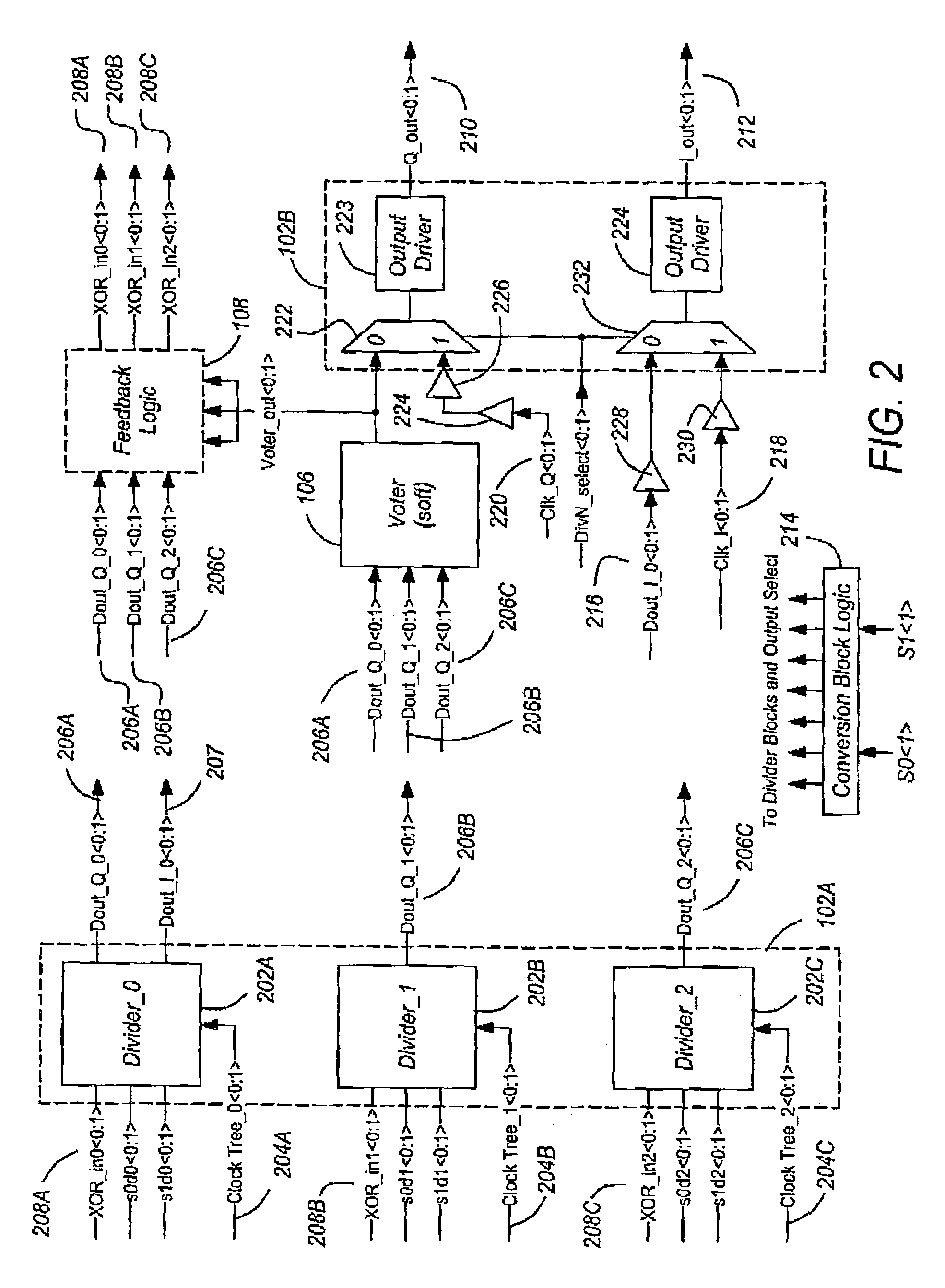
[0022]FIG. 2 is a...


PUM


Abstract

A radiation hard logic device such as a divider is disclosed. The logic device includes a voter module to determine an error free logic device output, a feedback module to generate a correction signal and provide the signal to a logic correction module to correct the erroneous device output at substantially the same time that the erroneous logic device is presented to the logic correction module.

Description

BACKGROUND OF THE INVENTION[0001]1. Field of the Invention[0002]The present invention relates to error-resistant digital logic devices, and in particular to a system and method for correcting errors in a logic device.[0003]2. Description of the Related Art[0004]Computer memory and other semiconductor components are susceptible to environmental effects that can cause them to fail. One class of failures occurs as a result of exposure to radiation, which is common in the space environment. Such radiation can be devastating to a satellite lacking adequate safeguards. When cosmic radiation passes through a sensitive semiconductor component in a satellite, one of three possible conditions may result.[0005]In a microprocessor or RAM chip, a single-event upset (SEU) can occur wherein the contents of a particular logical device such as a register or a divider become inverted (e.g. a bit flips from 0 to 1). As a result, sensor data can be corrupted, algorithms can fail, and the satellite firm...

Claims


Application Information

Patent Timeline
IPC IPC(8): G06F11/08G06F7/02G06F11/18
CPCG06F11/183
Inventor MAJUMDAR, RAHUL S.
Owner THE BOEING CO
Why Eureka
Try Eureka