Apparatus for reducing hydrocarbon emission of internal combustion engine

a technology of hydrocarbon emission and internal combustion engine, which is applied in the direction of machines/engines, combustion-air/fuel-air treatment, electric control, etc., can solve the problem of floating hc, and achieve the effect of reducing hc emission and reducing deterioration of hc absorbing characteristics

Inactive Publication Date: 2006-09-19
DENSO CORP +1
View PDF13 Cites 28 Cited by
  • Summary
  • Abstract
  • Description
  • Claims
  • Application Information

AI Technical Summary

Benefits of technology

[0007]The present invention is made in view of the foregoing matter and it is an object of the present invention to provide an apparatus capable of reducing a hydrocarbon emission.
[0010]While the engine is driven, the HC having a high boiling point and being blown back from the combustion chamber floats around the intake port. In the present invention, the HC absorbent is disposed away from the intake passage via the air suction passage, thus, the floating HC is not absorbed in the HC absorbent so that a deterioration of the HC absorbing characteristic of the HC absorbent is restricted. It is also restricted that the floating HC is introduced into the combustion chamber and exhausted as the unburned gas. That is, the reduction of the HC emission is effectively achieved.
[0013]While the engine is driven, the HC is not absorbed in the HC absorbent and a deterioration of HC absorbing characteristic is restrained since the HC absorbent is disposed at the place to where the floating HC does not flows. Thereby, it is restricted that the floating HC is introduced into the combustion chamber and exhausted as unburned gas. The reduction of HC emission is effectively achieved.

Problems solved by technology

It is also restricted that the floating HC is introduced into the combustion chamber and exhausted as the unburned gas.

Method used


Image

  • Apparatus for reducing hydrocarbon emission of internal combustion engine
  • Apparatus for reducing hydrocarbon emission of internal combustion engine
  • Apparatus for reducing hydrocarbon emission of internal combustion engine

Examples


first embodiment

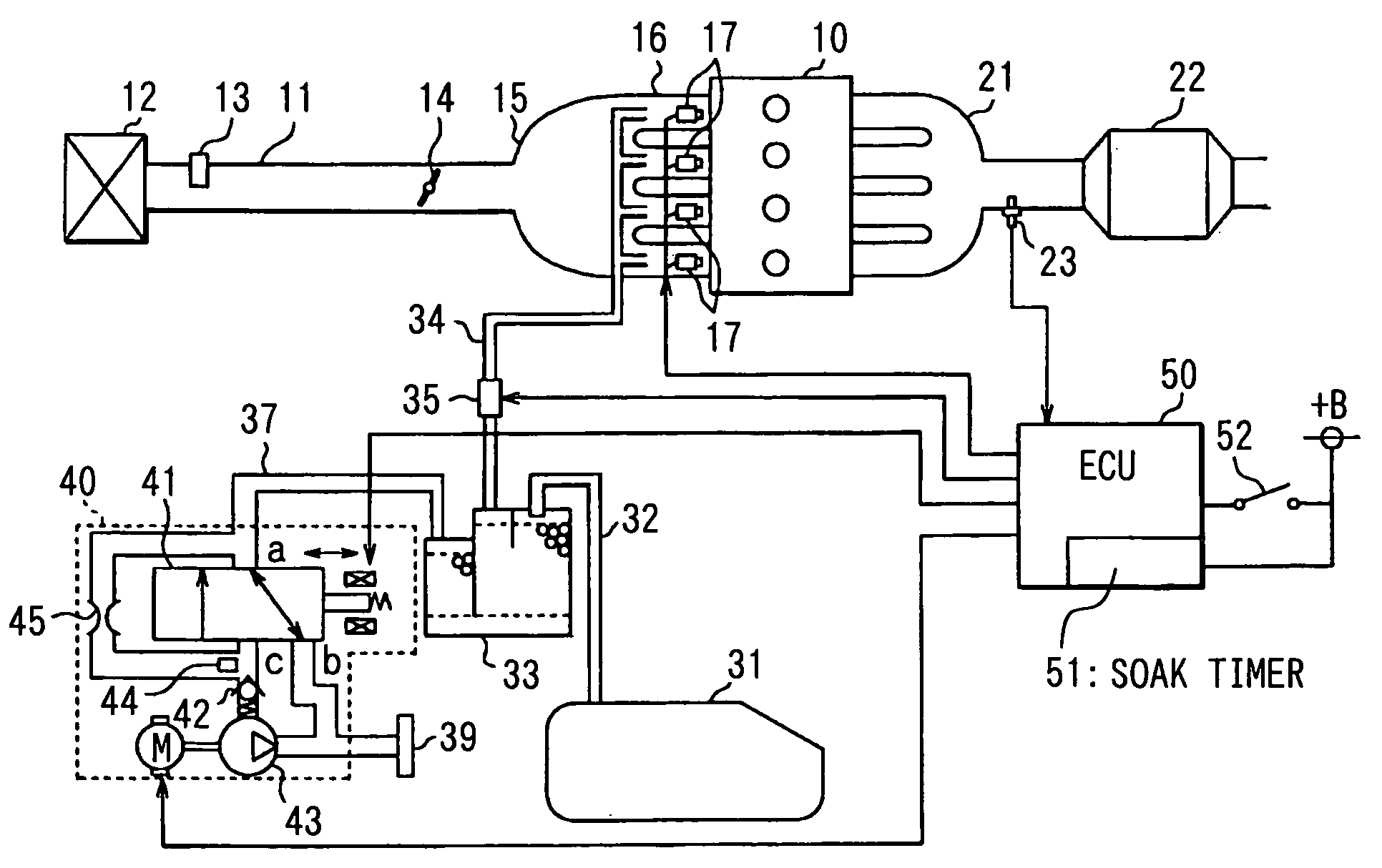
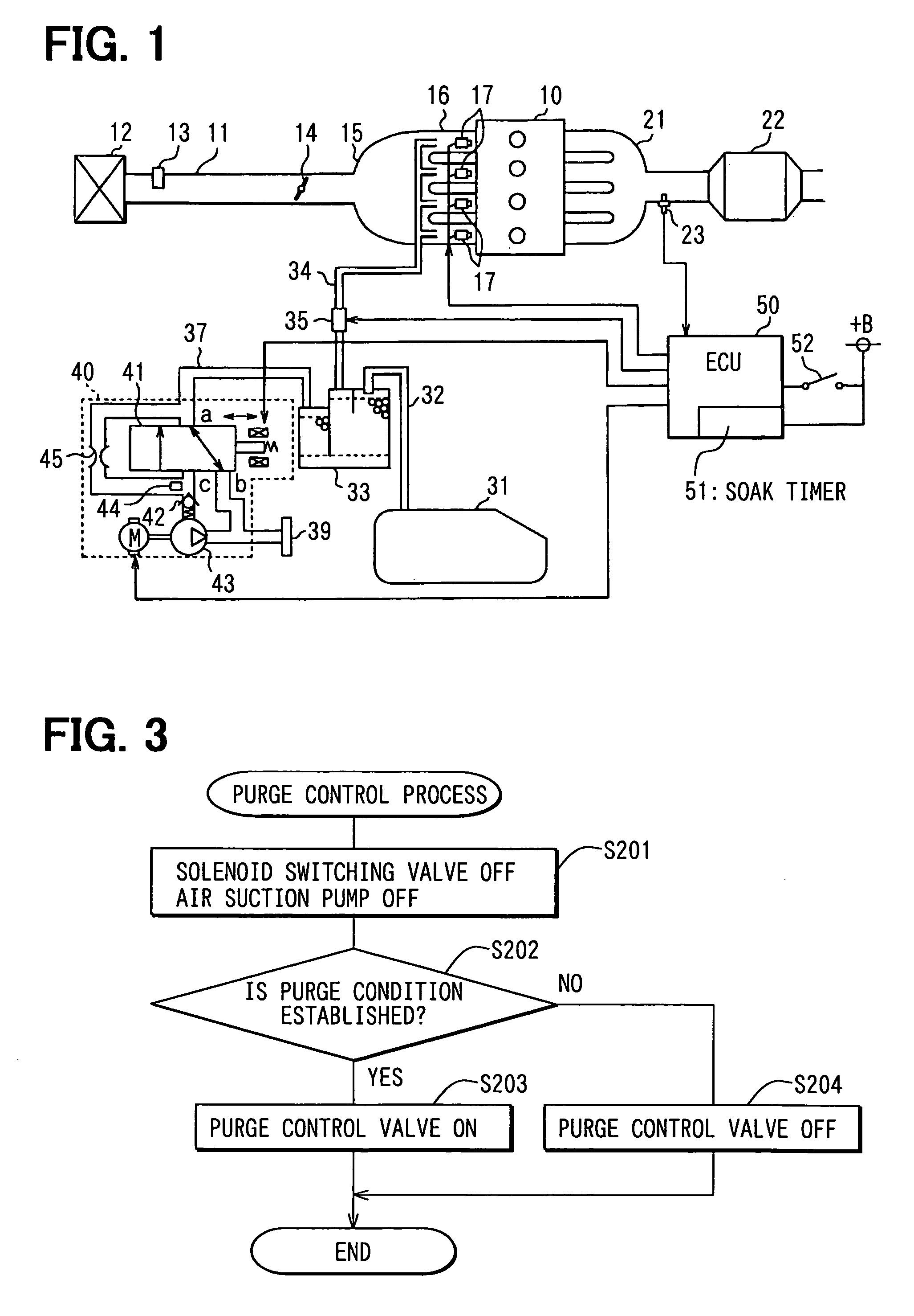
[0027]The present invention is applied to a four-cylinder gasoline injection engine. FIG. 1 is a schematic view showing an engine control system according to a

[0028]Referring to FIG. 1, an air-cleaner 12 is disposed at an inlet of an intake pipe 11, and airflow meter 13 for measuring the amount of air passing through the intake pipe 11 is disposed downstream of the air-cleaner 12 in the intake pipe 11. The airflow meter 13 is provided with an intake air temperature sensor (not shown). A throttle valve 14 is provided downstream of the airflow meter 13, which is controlled an opening degree thereof by a DC motor and the like. A surge tank 15 is connected with the intake pipe 11 downstream of the throttle valve 14. An intake manifold 16 for introducing an air into the each cylinder is connected with the surge tank 15. A fuel injector 17 is provided at each intake port of the intake manifold 16. An intake passage is comprised of the intake pipe 11, the surge tank 15 and the intake manif...

second embodiment

[0053]the present invention is described herein after.

[0054]Referring to FIG. 7, an air-cleaner 312 is disposed at an inlet of an intake pipe 311, and airflow meter 313 for measuring the amount of air passing through the intake pipe 311 is disposed in the intake pipe 311, the airflow meter 313 being disposed downstream of the air-cleaner 312. The airflow meter 313 is provided with an intake air temperature sensor (not shown) therein. A throttle valve 314 is provided downstream of the airflow meter 313, which is controlled an opening degree thereof by a throttle actuator 314a such as an DC motor and the like. A surge tank 315 is connected with the intake pipe 311 downstream of the throttle valve 314. An intake manifold 316 for introducing an air into the each cylinder is connected with the surge tank 315. A fuel injector 317 is provided at each intake port of the intake manifold 316. An intake passage is comprised of the intake pipe 311, the surge tank 315 and the intake manifold 316...


PUM


Abstract

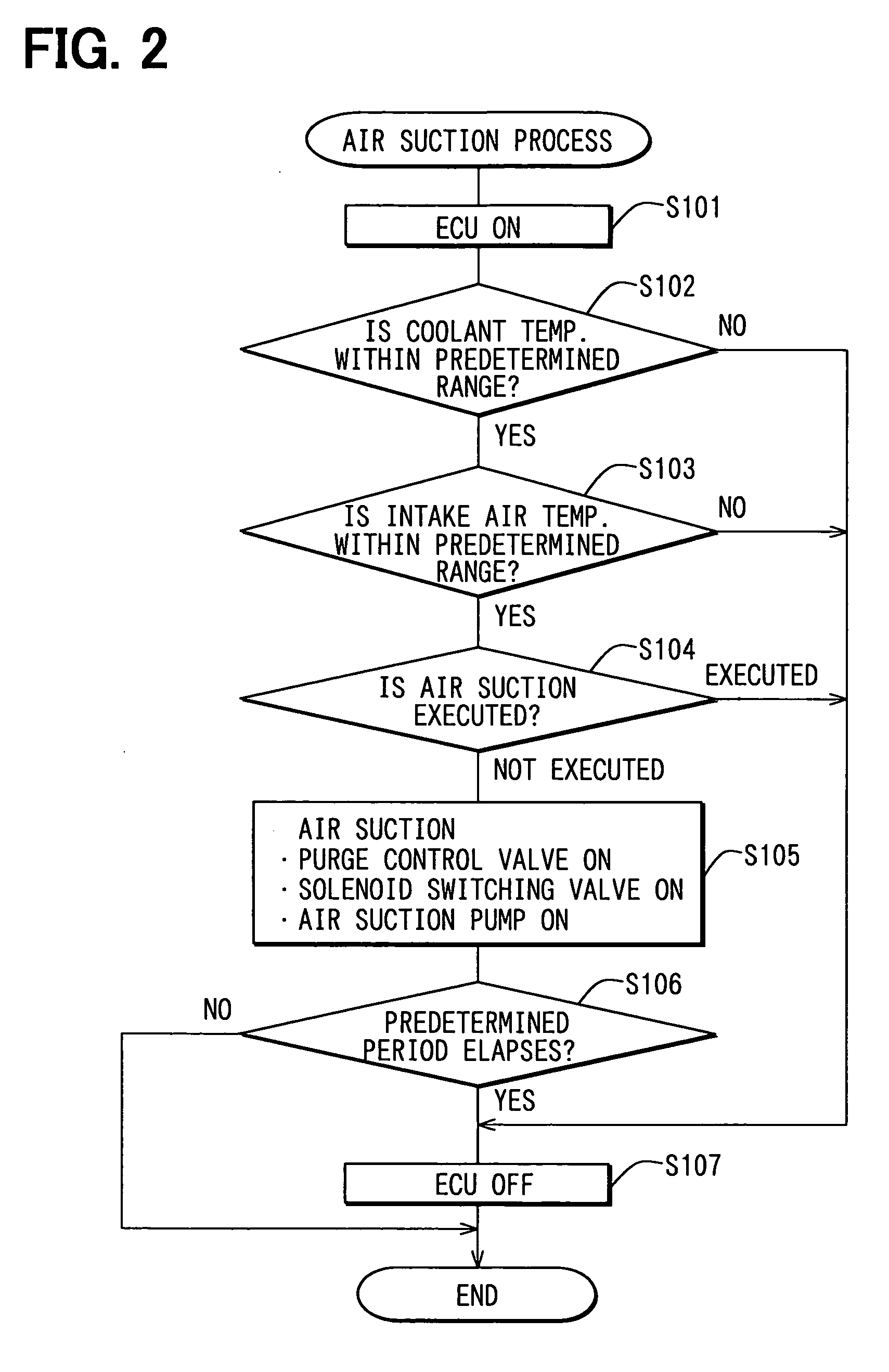
A canister communicates with an intake manifold of an internal combustion engine through a purge pipe. The canister absorbs fuel vapor evaporated in a fuel tank. The absorbed fuel vapor is purged into the intake manifold when the engine is on. A gas leak check module communicates with the canister for drawing air by an air suction pump 43. When the engine is off, the air suction pump is driven and draws hydrocarbon floating at a vicinity of an intake port through the purge pipe. Thus, the hydrocarbon floating at the vicinity of the intake port is absorbed in the canister so that emission of hydrocarbon is reduced.

Description

CROSS REFERENCE TO RELATED APPLICATION[0001]This application is based on Japanese Patent Application No. 2003-273733 filed on Jul. 11, 2003 and Japanese Patent Application No. 2003-273732 filed on Jul. 11, 2003, the disclosure of which are incorporated herein by reference.FIELD OF THE INVENTION[0002]The present invention relates to an apparatus for reducing hydrocarbon emission of an internal combustion engine. The hydrocarbon is referred to as HC herein after.BACKGROUND OF THE INVENTION[0003]In an internal combustion engine, when fuel leaks from a fuel injector, when fuel is blown back from an combustion chamber toward the intake port, or when fuel flows out from a positive crankcase ventilation passage, the fuel containing HC may remain around an intake port with the engine off. A multi-cylinder internal combustion engine, especially, has a remaining fuel in an intake manifold. After the engine is stayed for a certain period in such a state, the remaining fuel evaporates into a fl...

Claims


Application Information

Patent Timeline
Patent Type & Authority Patents(United States)
IPC IPC(8): F01N3/00F02M33/02F02D41/00F02D41/04F02M25/08
CPCF02D41/0032F02M25/0827F02D41/042F02M35/0218
Inventor ANNOURA, TOSHIKISUZUKI, HIDEKIHOSHI, KOICHIITOH, TAKAAKI
Owner DENSO CORP
Why Eureka
Try Eureka