Hydraulic rescue tool

a technology of hydraulic tools and tools, applied in the field of hydraulic tools, can solve the problems of increased resistance, enormous friction, and difficulty in achieving the above-mentioned procedures in the field without the proper equipmen

Inactive Publication Date: 2006-09-19
PATTON HYDRAULICS
View PDF16 Cites 29 Cited by
  • Summary
  • Abstract
  • Description
  • Claims
  • Application Information

AI Technical Summary

Benefits of technology

[0022]A final object of the invention is that an area of the piston is enlarged to provide additional power on the inward stroke of the implement unit. Standard hydraulic cylinders normally have the area of the inward stroke reduced by the diameter of the piston rod. The instant invention, on the other hand, has a piston rod with a rebated diameter that is two times smaller than a normal piston, which provides additional surface area for hydraulic pressure when retracting an implement unit.

Problems solved by technology

It is obvious that the above procedures are difficult to accomplish in the field without the proper equipment, as was evidenced at the September 11 rescue site when factory maintenance teams were required to be sent to keep the tools functioning.
Other problems are encountered as a result of the extreme torque on the bolt which creates tremendous compression between the blades.
The problems include lubrication and resistance of the blades when the high torque holds the cutting surfaces against each other, which tends to squeeze lubrication from the blades, thus causing galling and hence greater resistance.
The tightness of the fit between the blades also causes an enormous amount of friction which adds excessive resistance to the hydraulic forces driving the tool.
The excessive resistance robs the energy from the cutting action, and presents the possibility of blade failure at the pivot.
Training and practice with the tool is necessary to compel the operator to be cautious and aware that his / her hand may be trapped, with the tool causing considerable personal injury.
Further, it is necessary to heat treat the scissor blades to maintain a sharp edge for cutting metal, which makes the blades brittle and easy to break.
When the blades loose their edge, twisting becomes more apparent and cutting is very inefficient, which requires immediate repair or replacement.
Another extreme danger to the operator is blade failure when the blades twist, as they tend to become separated by the material being cut, thereby causing them to fracture, snap, bend or completely sever.
When a cutter blade breaks, the broken piece may fly at high speed toward the operator or other rescue personnel, thus causing severe injury or even a fatality.
It is well known that operators have sustained both minor to major injuries on the past from flying blades that have broken during extrications.

Method used


Image

  • Hydraulic rescue tool
  • Hydraulic rescue tool
  • Hydraulic rescue tool

Examples


Embodiment Construction

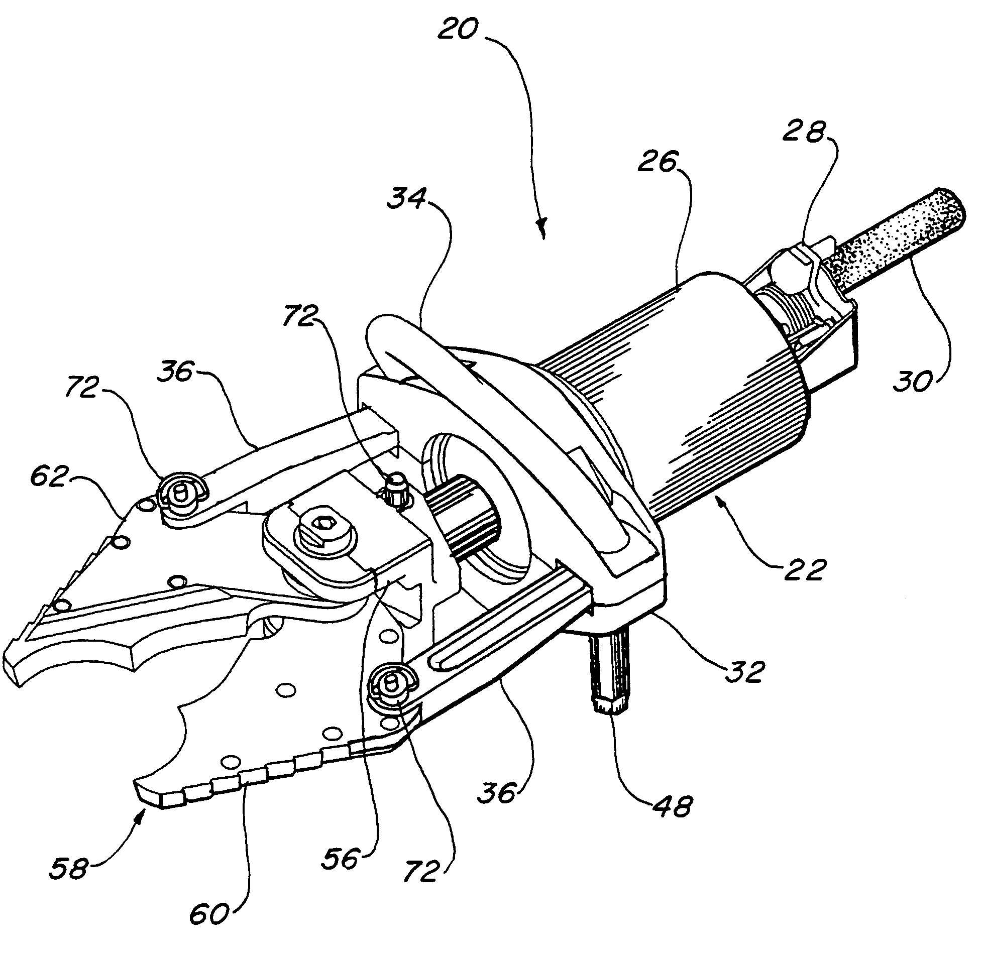
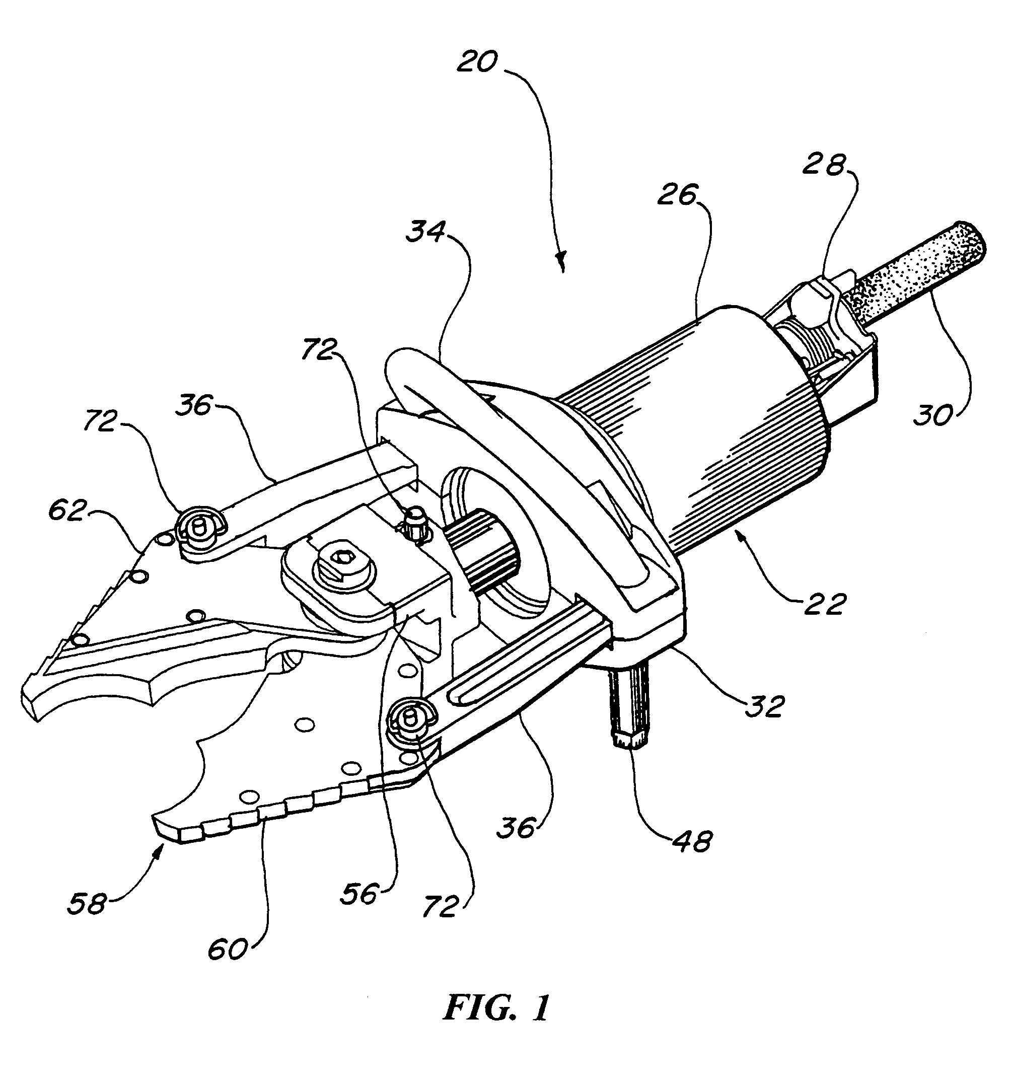
[0041]The best mode for carrying out the invention is presented in terms of a preferred embodiment. The preferred embodiment, as shown in FIGS. 1 through 17, is comprised of a rescue tool 20, preferably using hydraulics in the form of a hydraulic cylinder 22 including a piston rod 24 within a cylinder housing 26 creating the requisite linear drive means. The piston rod 24 extends outward and retracts inward, thus creating a pushing and pulling action. It should be noted, however, that while the hydraulic cylinder 22 is the preferred means, other methods may be used with equal ease, such as pneumatic cylinders, electric linear drive mechanisms, pyrotechnic devices, or any drive that utilizes a ram or arm that moves in a linear direction.

[0042]For convenience of operation, hydraulic controls 28 for the cylinder are attached at the end of the cylinder 22, opposite the piston rod 24, as shown in FIGS. 1–4. The controls 28 cause the piston rod 24 to extend or retract and are well known i...


PUM

PropertyMeasurementUnit
diameteraaaaaaaaaa
forceaaaaaaaaaa
torquesaaaaaaaaaa

Abstract

A hydraulic rescue tool (20) that utilizes a hydraulic cylinder (22) having a piston rod (24) that is movably disposed within the housing of the cylinder to provide linear driving means for the rescue tool. A cylinder yoke (32) is rotatably attached to the hydraulic cylinder housing and includes a front handle bar (34) for manipulating the tool. Rotation of the cylinder yoke (32) relative to the cylinder (22) prevents injury to an operator in the event that the tool binds and torques. An implement unit (50), which is either a cutter (54) or a spreader (74), is detachably disposed onto the piston rod (24). Pivotal links (36) connect the unit (50) to the cylinder yoke (32), with the unit used for cutting or spreading metal during a rescue. A plurality of quick release pins (72) attach the implement unit (50) to the piston rod (24) and pivotal links, thus providing a rapid release of the implement unit (50) from the piston rod (24) and links (36) for replacement or repair. The piston rod (24) has a rebated diameter (82) on its internal end that is at least two times smaller than the piston. This reduction in diameter provides additional surface area for hydraulic pressure when retracting an attached implement unit.

Description

TECHNICAL FIELD[0001]The invention generally pertains to rescue tools used for emergency rescue operations, and more specifically to a hydraulic tool that provides spreading, crushing or cutting with a quick detachable blade or spreader unit.BACKGROUND ART[0002]Previously, many types of rescue tools have been used to provide an effective means to pry or cut open a damaged vehicle at the scene of an accident. Other machine tools have also been developed with similar operational characteristics.[0003]A search of the prior art did not disclose any patents that read directly on the claims of the instant invention, however the following U.S. patents are considered related:[0004]U.S. Pat. No.InventorIssue Date6,244,568PattonJun. 12, 20015,956,992PattonSep. 28, 19995,622,353Painter et al.Apr. 22, 19975,301,533JacksonApr. 12, 19944,734,983BrickApr. 5, 19884,392,263AmorosoJul. 12, 19834,333,330PorterJun. 8, 1982[0005]Patton's own U.S. Pat. No. 6,244,568 teaches a rescue spreading tool that p...

Claims


Application Information

Patent Timeline
Patent Type & Authority Patents(United States)
IPC IPC(8): B21D41/02
CPCA62B3/005Y10S72/705
Inventor PATTON, TOMMY L.ANKERSTAR, DONALD L.
Owner PATTON HYDRAULICS
Why Eureka
Try Eureka