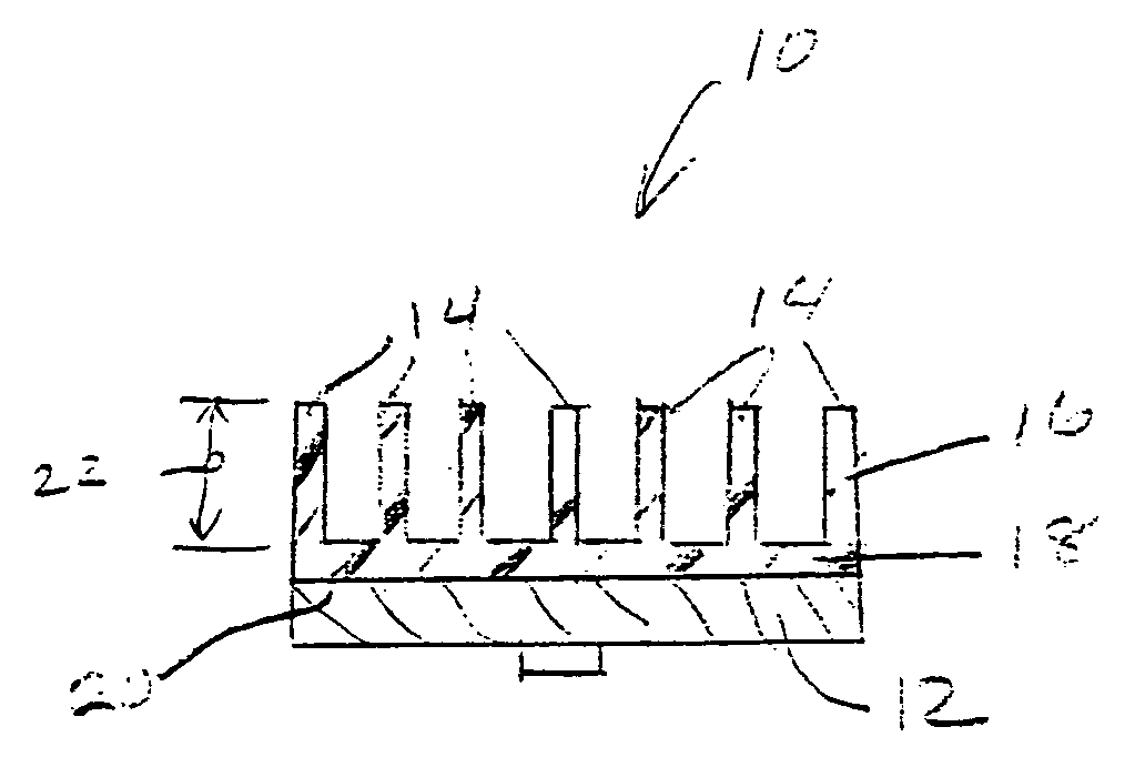
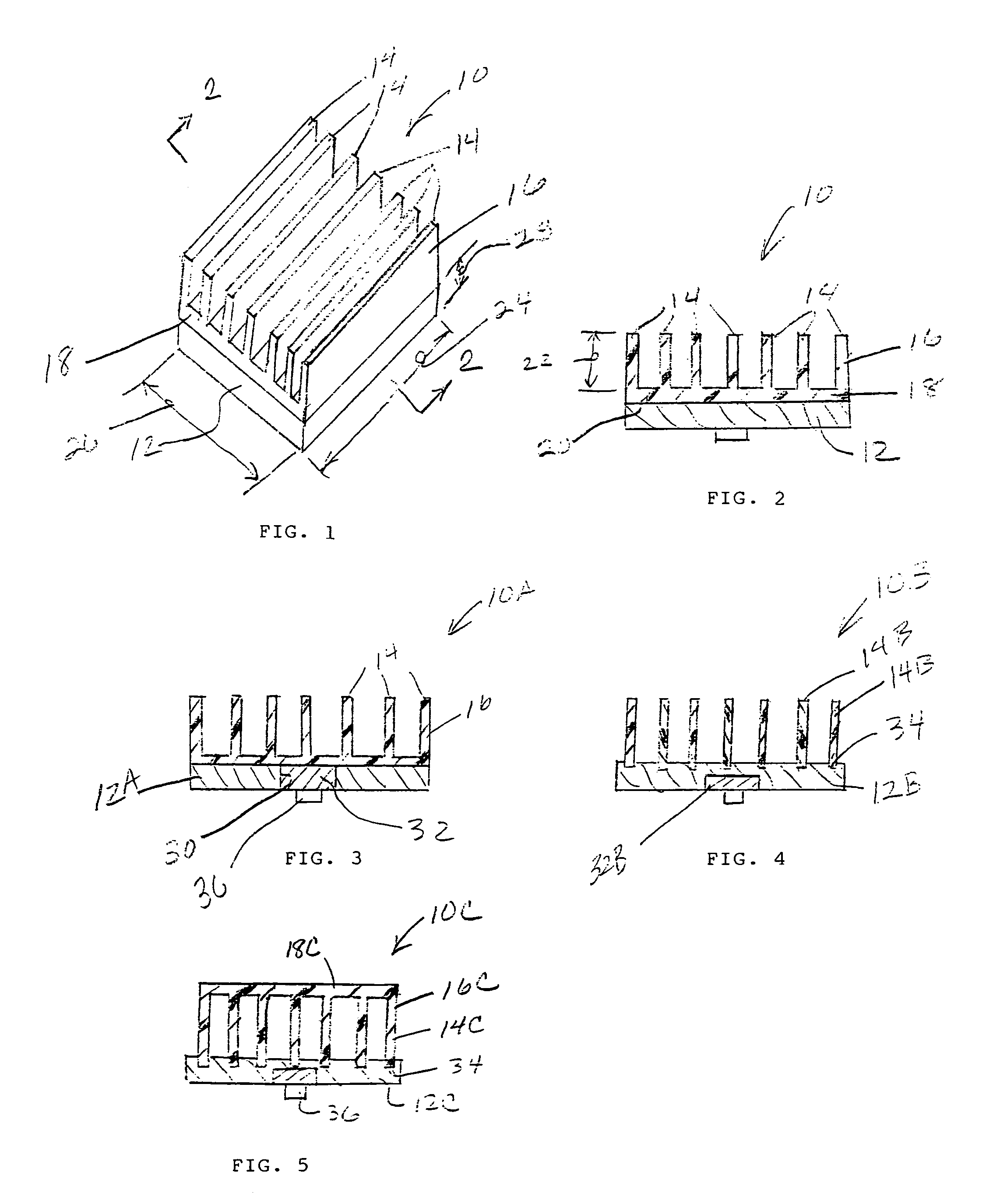
Optimized heat sink using high thermal conducting base and low thermal conducting fins

a heat sink and low-temperature technology, applied in the field of heat sinks, can solve problems such as system failure, affecting the performance of the overall system, and affecting the performance of the individual components,

Inactive Publication Date: 2006-09-19
NEOGRAF SOLUTIONS LLC
View PDF19 Cites 58 Cited by
  • Summary
  • Abstract
  • Description
  • Claims
  • Application Information

AI Technical Summary

Benefits of technology

[0025]And another object of the present invention is the provision of

Problems solved by technology

However, microprocessors, integrated circuits and other sophisticated electronic components typically operate efficiently only under a certain range of threshold temperatures.
The excessive heat generated during operation of these components can not only harm their own performance, but can also degrade the performance and reliability of the overall system and can even cause system failure.
The increasingly wide range of environmental conditions, including temperature extremes, in which electronic systems are expected to operate, exacerbates the negative effects of excessive heat.
The use of copper or aluminum heat dissipating elements can present a problem because of the weight of the metal, particularly when the heat transmitting area of the heat dissipating component is significantly larger than that of the electronic device.
If metallic he

Method used


Image

  • Optimized heat sink using high thermal conducting base and low thermal conducting fins
  • Optimized heat sink using high thermal conducting base and low thermal conducting fins
  • Optimized heat sink using high thermal conducting base and low thermal conducting fins

Examples


example

[0057]Graphite sheets with a weight per unit area of 70 mg / cm2 with dimensions of approximately 30 cm by 30 cm were impregnated with epoxy such that the resulting calendered mats were 12 weight % epoxy. The epoxy employed was a diglycidyl ether of bisphenol A (DGEBA) elevated temperature cure formulation and the impregnation procedures involved saturation with an acetone-resin solution followed by drying at approximately 80° C. Following impregnation, the sheets were then calendered from a thickness of approximately 7 mm to a thickness of approximately 0.4 mm and a density of 1.63 g / cm3. The calendered, impregnated sheets were then cut into disks with a diameter of approximately 50 mm and the disks were stacked 46 layers high. This stack of disks was then placed in a TMP (Technical Machine Products) press, and cured at 2600 psi at 150° C. for 1 hour. The resultant laminate had a density of 1.90 g / cm3, a flexural strength of 8000 psi, a Young's modules of 7.5 Msi (millions of pounds ...


PUM

PropertyMeasurementUnit
Poweraaaaaaaaaa
Heightaaaaaaaaaa
Temperatureaaaaaaaaaa

Abstract

An optimized design for a composite heat sink is provided utilizing a high thermal conducting base and low thermal conducting fins. The base preferably is constructed from anisotropic graphite material, and the fins are preferably constructed from a thermally conductive plastic material. In the case of a low profile heat sink having a fin height of no greater than about 3 times that of the base, the composite construction provides superior cooling yet lighter weight as compared to a conventional all-aluminum heat sink of the same dimensions.

Description

RELATED APPLICATION[0001]This application is a continuation-in-part of and commonly assigned U.S. patent application having Ser. No. 10 / 113,381, filed Mar. 29, 2002, now abandoned the disclosure of which is incorporated herein by reference.TECHNICAL FIELD[0002]The present invention relates to a heat sink capable of managing the heat from a heat source such as an electronic device.BACKGROUND OF THE INVENTION[0003]With the development of more and more sophisticated electronic devices, including those capable of increasing processing speeds and higher frequencies, having smaller size and more complicated power requirements, and exhibiting other technological advances, such as microprocessors and integrated circuits in electronic and electrical components and systems as well as in other devices such as high power optical devices, relatively extreme temperatures can be generated. However, microprocessors, integrated circuits and other sophisticated electronic components typically operate...

Claims


Application Information

Patent Timeline
IPC IPC(8): F28F7/00H05K7/20F28F3/02F28F21/06H01L23/367H01L23/373
CPCF28F3/048F28F21/06H01L23/367H01L23/3672H01L23/3737H01L2924/0002Y10S165/905H01L2924/00
Inventor KRASSOWSKI, DANIEL W.CHEN, GARY G.
Owner NEOGRAF SOLUTIONS LLC
Why Eureka
Try Eureka