Device and process for electrodialysis of ultrafiltration premeate of electrocoat paint

a technology of electrodialysis and ultrafiltration, applied in electrodialysis, refrigeration machines, refrigeration components, etc., can solve the problems of increasing the time between electrode cleaning or replacement of objects, and achieve the effects of reducing the deposition of paint solids, enhancing the mass transfer of solubilizer, and increasing the velocity in the annular spa

Inactive Publication Date: 2006-09-19
CELTECH
View PDF3 Cites 4 Cited by
  • Summary
  • Abstract
  • Description
  • Claims
  • Application Information

AI Technical Summary

Benefits of technology

[0022]A sixth improvement is achieved by recirculating at least a portion of the treated permeate through the cell for a predetermined time period at a rate so as to increase the velocity in the annular space between the membrane and the object electrode. This serves to enhance mass transfer of the solubilizer through

Problems solved by technology

Since coating of the object electrode with paint pigment and resin is typically the limiting factor in the operation of the system

Method used


Image

  • Device and process for electrodialysis of ultrafiltration premeate of electrocoat paint
  • Device and process for electrodialysis of ultrafiltration premeate of electrocoat paint
  • Device and process for electrodialysis of ultrafiltration premeate of electrocoat paint

Examples


Embodiment Construction

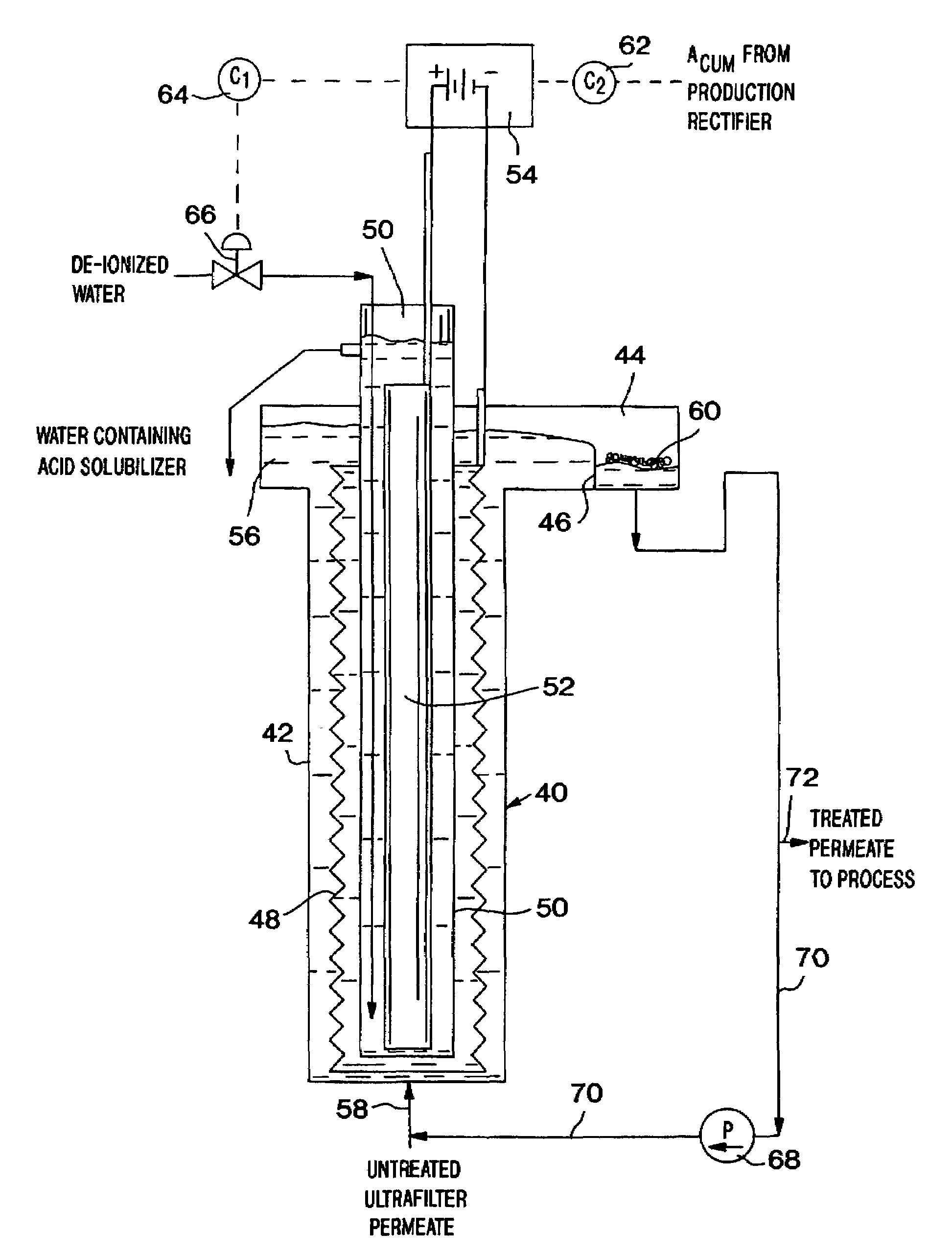
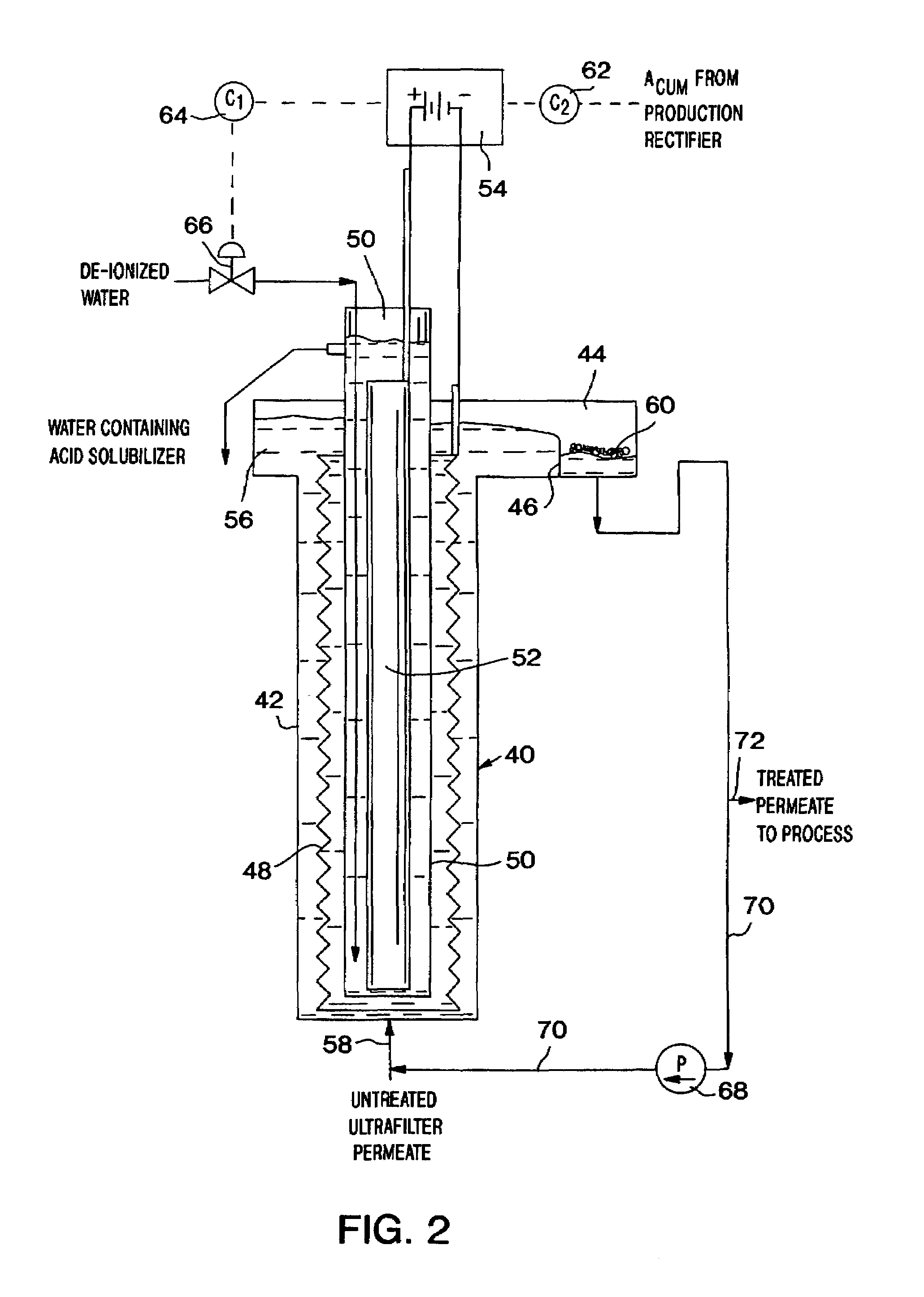
[0027]Specifically, the electrical resistance of the cell and the minimization of solids precipitation at the object electrode determine certain area ratios between the system elements for optimum performance. A workable and commercially practicable design has been developed in which the object electrode-to-counter electrode area ratio is at least about 6, and preferably about 6 to about 7. A particularly preferred counter electrode has an outside diameter of about 1.9 inches, the ion exchange membrane has an inside diameter of about 2.9 inches and the object electrode has an outside diameter of about 4 inches. Moreover, a preferred object electrode is made of a reticulated material so that its actual surface is approximately 3.2 times its apparent cross sectional area. With this combination of dimensions, the ratio of object electrode area (Ao) area to counter electrode area (Ac) is equal to about 6.7. Previous research has shown that preferred counter electrode current density is ...


PUM

PropertyMeasurementUnit
Ratioaaaaaaaaaa

Abstract

An electrodialysis cell (40) suitable for removal of paint solubilizer from electrocoat paint ultrafilter permeate includes a tubular, non-conductive housing (42), a substantially cylindrical, hollow object electrode (48) in the housing, a substantially cylindrical counter electrode (52) situated within the hollow object electrode, and a tubular ion exchange membrane (50) around the counter electrode but spaced from the counter electrode as well as the object electrode. The counter electrode and the tubular membrane together define an annular electrolyte passageway while the object electrode and the tubular membrane together define an annular ultrafilter permeate passageway. The object electrode-to-counter electrode area ratio is at least about 6.

Description

CROSS-REFERENCE TO RELATED APPLICATION[0001]This application is a 371 of PCT / US01 / 04886, filed Feb. 15, 2001, which claims the benefit of U.S. Provisional Application No. 60 / 182,681, filed on Feb. 15, 2000.TECHNICAL FIELD OF THE INVENTION[0002]This invention relates to electrocoating systems and process.BACKGROUND OF THE INVENTION[0003]In the process known as electrocoating or electrodeposition painting, paint solids (pigment and resin) are maintained in solution or as a colloidal suspension by a counter-ion that functions as the solubilizer. In most cases, the paint solids are positively charged, or cationic, and the solubilizer counter-ion is an anion (called cathodic electrocoat). However, in some systems the paint solids are anodic and the counter-ion solubilizer is the cation (called anodic electrocoat). The design and principles disclosed here can apply to either. The examples and design specifics are therefore expressed in terms of the “object electrode”, which is the item or...

Claims


Application Information

Patent Timeline
IPC IPC(8): C25D17/00B01D61/46B01D61/44B01D61/54B01D61/58C02F1/44C02F1/469C02F9/00C25D13/24
CPCB01D61/44B01D61/46B01D61/54B01D61/58C25D13/24B01D61/145C25D21/22C02F1/444C02F1/469C02F9/00C02F2103/14C02F2201/003C02F2201/46115C02F2201/46185B01D61/422
Inventor LEGATSKI, L. KARLLEGATSKI, ERIC M.
Owner CELTECH
Why Eureka
Try Eureka