Apparatus for remote control of a microscope

a microscope and remote control technology, applied in the field of microscope remote control apparatus, can solve the problems of not being completely automated, unable to ensure and unable to achieve the effect of ensuring that one could go back

Inactive Publication Date: 2006-09-19
OLYMPUS AMERICA
View PDF79 Cites 50 Cited by
  • Summary
  • Abstract
  • Description
  • Claims
  • Application Information

AI Technical Summary

Benefits of technology

[0014]In accordance with the present invention, a person such as a pathologist at a computer terminal may control an automated microscope to acquire on a computer screen or window images of the specimen at different magnifications as selected by the person. Further, the person may receive on the screen a low magnification, reconstructed image of the entire specimen to aid the person in interactively selecting points of interest on the specimen, such as along a basal layer of a tissue specimen.

Problems solved by technology

In the image analysis and quantification of DNA from tissue sections as disclosed in U.S. Pat. No. 4,741,031, and also especially in the immunohisto-chemistry assays on the kinds of cell analysis systems disclosed in U.S. Pat. Nos. 5,086,476; 5,202,931; and 5,252,487 issued to Bacus, there is a problem of first locating the cancer regions for analysis under low power and then remembering them when performing the analysis under higher power.
Specifically, the problem is that once the microscope is set up for quantification by image analysis under, e.g. 40×, where all of the diaphragms are set and light adjusted, etc., if the operator needs to move to another tissue area, it is first desirable to locate it at e.g. 10×.
Currently, there is no way to ensure that one could go back to the settings at the previous 40× magnification and continue on with the quantitative image analysis of that same specimen.
This necessitates finding those areas under 40×, without changing objectives, which is very slow and time-consuming, and often important cancer areas can be missed.
Also, another problem with tissue analysis, at its current state-of-the-art, is that it is not completely automated, for example, with regard to finding structural regions such as glands, basal layers or other important diagnostic regions.
Those particular microscopes lack a computer-controlled X and Y stage for translating a specimen-carrying slide with respect to the field of view of the selected objective lens.
When observing at high magnifications, the field of view is limited to very small area of the specimen.
Hence, the observer has difficulty in knowing and remembering the actual, exact location of this small periscopic view within the very large whole specimen.
Often, also the problem is finding or locating the tissue or cells for view at high magnification so that artifacts and / or blank spaces on the slide are not viewed.
This system is fairly or too slow for many uses.
A very expensive system is currently in use in which a pathologist located at a diagnostic center is able to make a diagnostic opinion with respect to specimens under a microscope at a remote center.
This system requires each subscriber to have a special microscope operable by manipulation of the robotic controls at the diagnostic center and a dedicated or large bandwidth channel to convey real time video signals and hence results in a very high cost for the assay being done.
This does not help the pathologist locate suspicious areas of interest as in a prescreening of the entire tissue.
Also, there is no image analysis quantitative testing from the received images at the diagnostic center; and no quantitative assaying is done with these images at the diagnostic center.
One problem with trying to do any transmission of digitized, microscopic, highly magnified images over the Internet is that the bandwidth is too narrow to accommodate the tremendous amount of stored data which needs to be transmitted.

Method used


Image

  • Apparatus for remote control of a microscope
  • Apparatus for remote control of a microscope
  • Apparatus for remote control of a microscope

Examples


Embodiment Construction

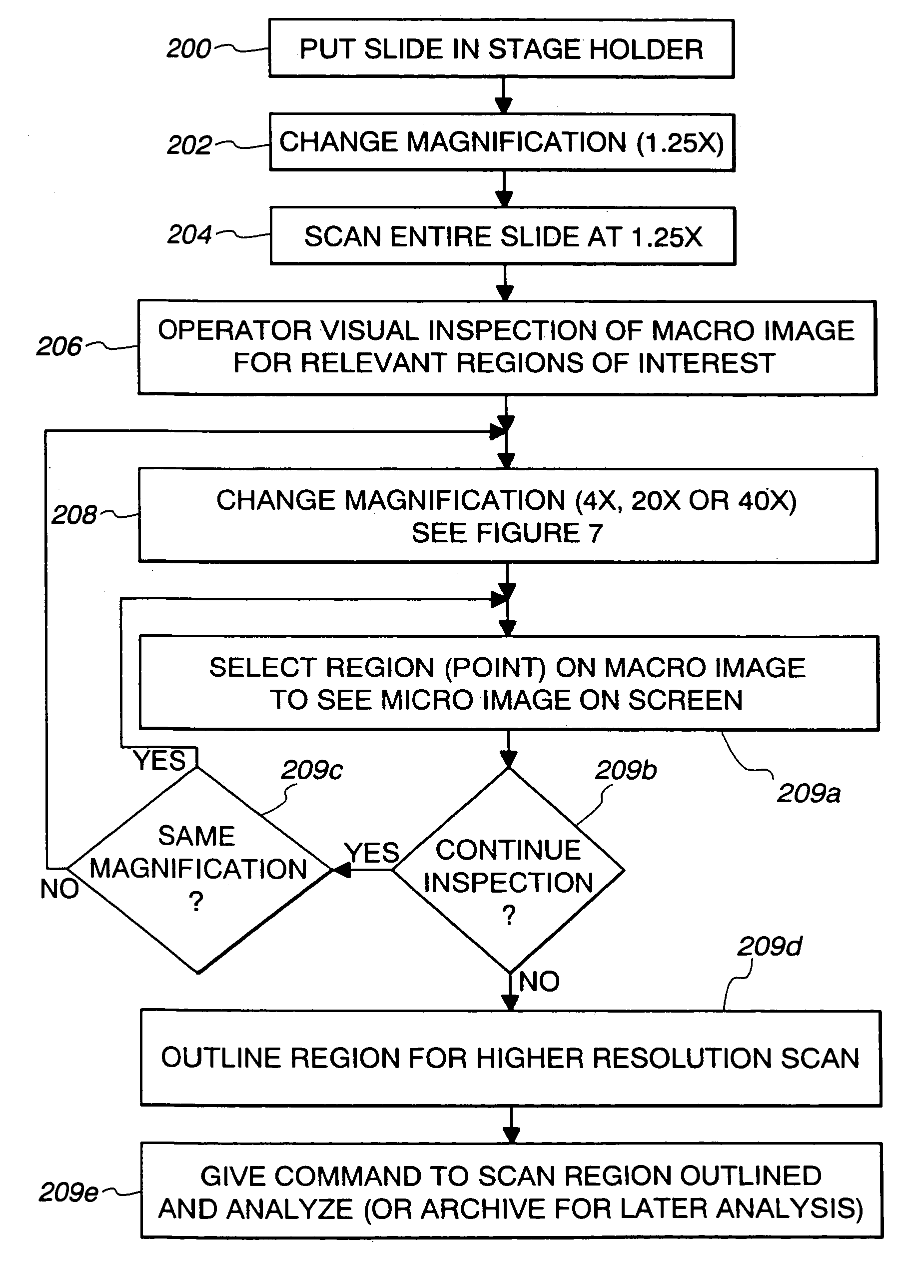
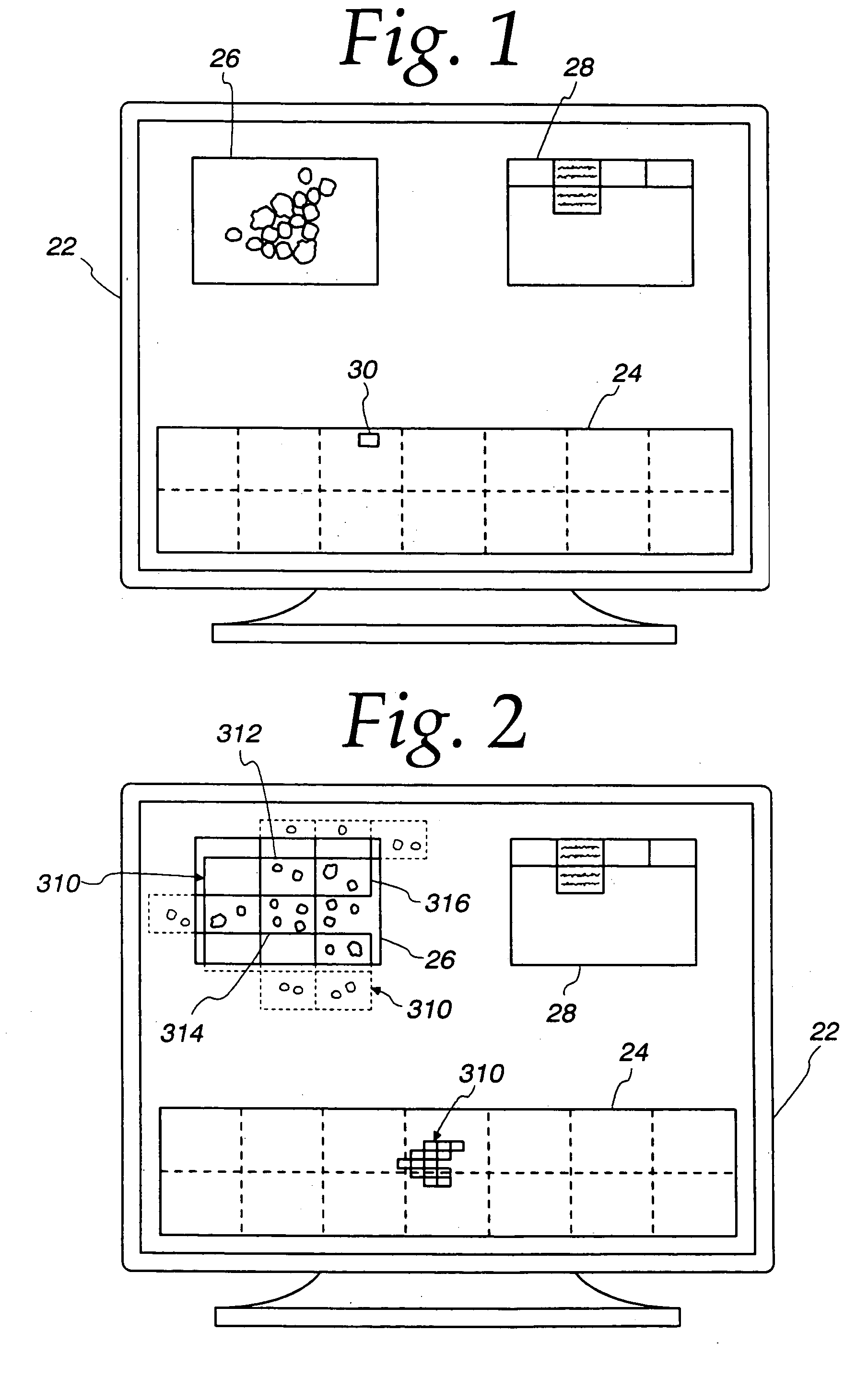
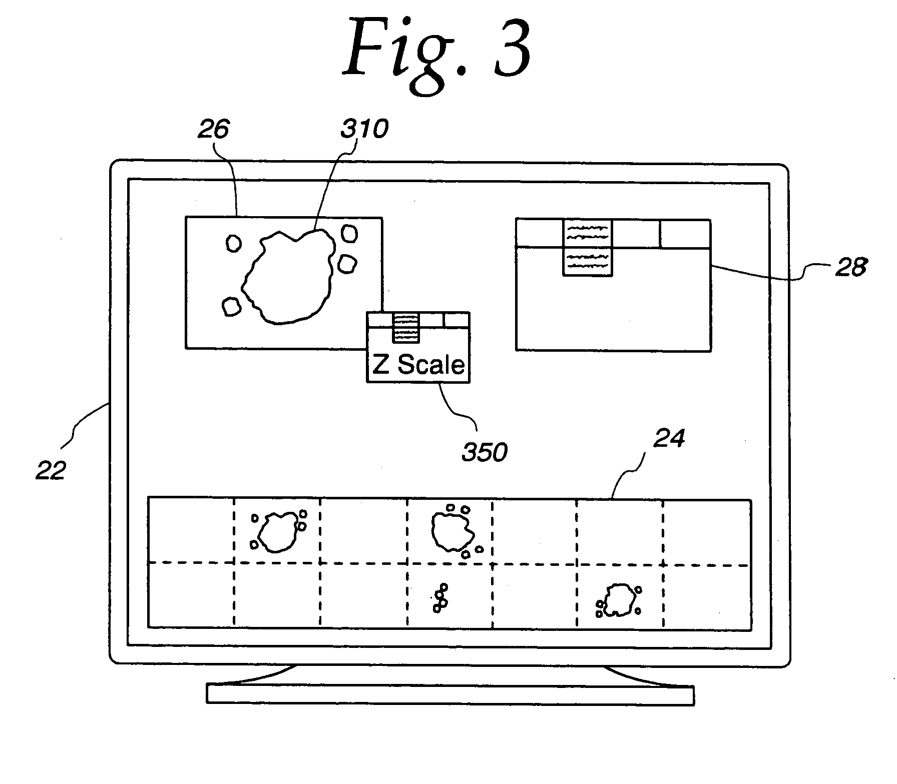
[0044]Referring now to the drawings, and especially to FIGS. 4 and 5, apparatus for synthesizing low magnification and high magnification microscopic images is shown therein and generally identified by reference numeral 10. The system includes a computer 12 which is a dual Pentium Pro personal computer in combination with a Hitachi HV-C20 video camera 14 associated with a Zeiss Axioplan 2 microscope 16. The computer system 12 is able to receive signals from the camera 14 which captures light from the microscope 16 having a microscope slide 18 positioned on an LUDL encoded motorized stage 20. The encoded motorized stage 20 includes a MAC 2000 stage controller for controlling the stage in response to the computer 12. A microscope slide 18 includes a biological specimen 21 which is to be viewed by the microscope and whose image is to be digitized both at low magnification and at high magnification as selected by a user. The low magnification digitized image is then displayed on a 21 in...


PUM

PropertyMeasurementUnit
imagingaaaaaaaaaa
microscope imagingaaaaaaaaaa
poweraaaaaaaaaa

Abstract

An apparatus and method acquires and stores multiple resolution images from a specimen on a support and provides to the user a low magnification, reconstructed macro image of the entire specimen, or a large portion thereof, to aid the person in selecting points of interest to be viewed or analyzed at higher magnifications and resolution. The reconstructed image is formed of a large number of tiled, stored images which are coordinated and assembled to form the macro image of the specimen which is displayed on a monitor. Preferably, the stored, reconstructed image is reduced further in size by a software system before it is displayed to the user. The display may be on a local monitor over a local area network or sent over the Internet to the user who is typically a pathologist. The user selects by a marker such as a cursor the defined area of interest or region and then views higher magnification images or has them analyzed. Preferably, the pathologist can scroll to shift digitized, adjacent image tiles into view on the monitor. A fully computer-controlled microscope is used to acquire and store the digitized images and the illustrated microscope can be remotely controlled to change objective lenses, focus, light intensity, filters, field diaphragm, and to shift the microscope stage by a controller.

Description

[0001]This is a continuation of a application, U.S. patent application Ser. No. 10 / 008,519, filed Nov. 13, 2001 now U.S. Pat. No. 6,674,884, which is a continuation of U.S. patent application Ser. No. 09 / 752,022 filed Dec. 28, 2000 now U.S. Pat. No. 6,404,906, which is a divisional application of U.S. patent application Ser. No. 09 / 395,694, filed Sep. 13, 1999, now U.S. Pat. No. 6,226,392, which is a continuation of U.S. patent application Ser. No. 08 / 805,856, filed Mar. 3, 1997, now U.S. Pat. No. 6,101,266 which is a continuation-in-part of U.S. patent application Ser. No. 08 / 701,974 filed on Aug. 23, 1996, now U.S. Pat. No. 6,031,930.FIELD OF THE INVENTION[0002]This invention relates to a method of, and an apparatus for, acquiring and constructing tiled digital images from a specimen on a support, such as a microscope slide, and for storing, and transferring the image for viewing by another at a local or remote location.BACKGROUND OF THE INVENTION[0003]In the image analysis and qu...

Claims


Application Information

Patent Timeline
Patent Type & Authority Patents(United States)
IPC IPC(8): G06K9/00A61B1/06G02B21/00A61B1/00G01N15/14G06F19/00G06T3/40G06T7/00
CPCG01N15/1475G06F19/321G06F19/3406G06T7/0012G06K9/00127G06T3/4038G06F19/3418G16H40/63G16H30/20G16H30/40G06V20/69G16H10/40
Inventor BACUS, JAMES V.BACUS, JAMES W.
Owner OLYMPUS AMERICA
Why Eureka
Try Eureka