Correction method for sensor output

a correction method and sensor technology, applied in the field of sensor correction methods, can solve the problems of unsuitability of quantitative measurements of sensors lacking linearity, and achieve the effect of low cos

Inactive Publication Date: 2006-09-19
ARKRAY INC
View PDF12 Cites 12 Cited by
  • Summary
  • Abstract
  • Description
  • Claims
  • Application Information

AI Technical Summary

Benefits of technology

[0040](2) In comparison with a device that needs a mechanical driving system, the speed in which the entire image is picked up is faster, making it possible to provide high-speed measuring processes.
[0041](3) It is possible to achieve low costs since no mechanical driving system is required.

Problems solved by technology

Those sensors that lack linearity have been considered to be unsuitable for quantitative measurements.

Method used


Image

  • Correction method for sensor output
  • Correction method for sensor output
  • Correction method for sensor output

Examples


embodiment 1

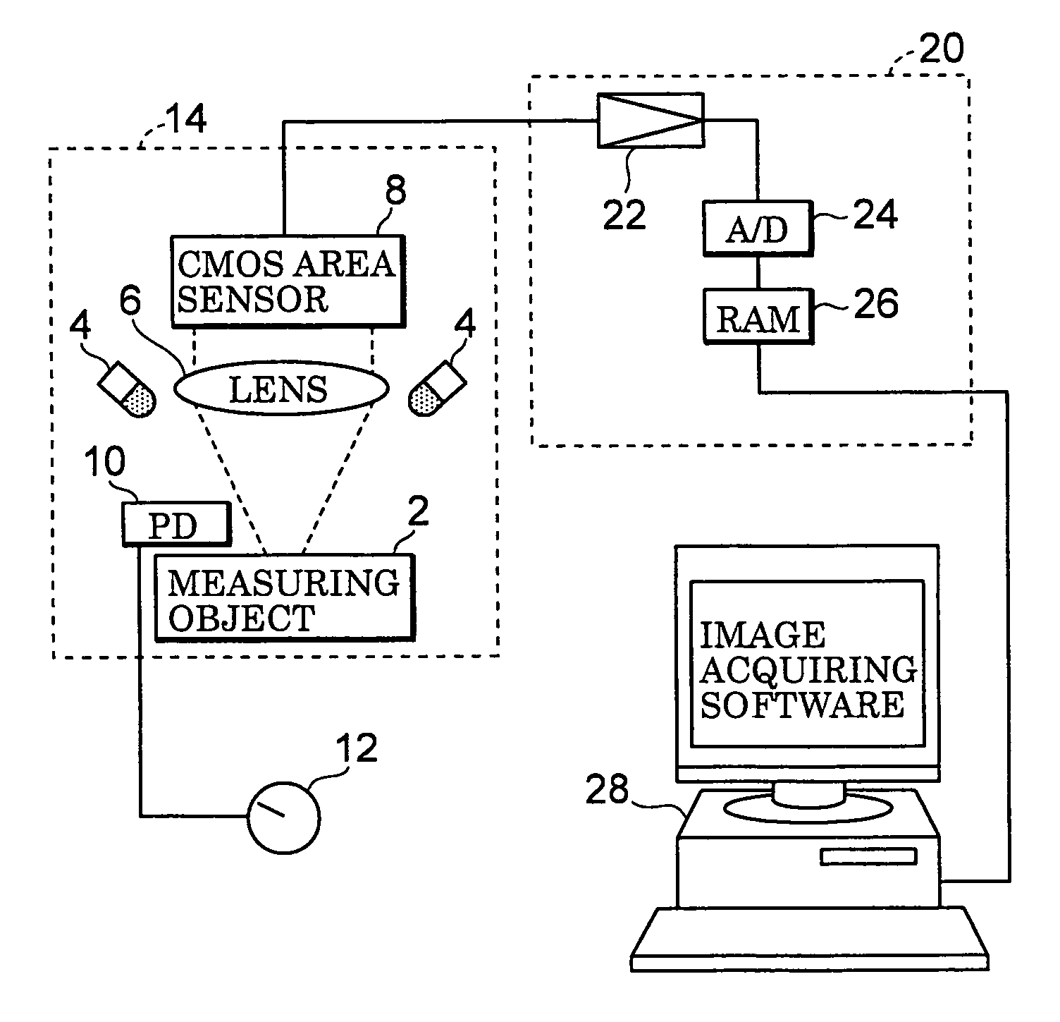
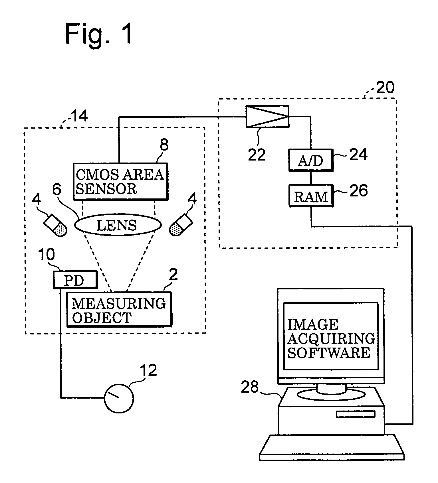
[0067]With respect to a first embodiment, FIG. 1 schematically shows one example of a two-dimensional reflection-factor measuring device to which an output correction method in accordance with the first aspect of the present invention is applied with an area sensor being used as the sensor.

[0068]Reference numeral 2 is a measuring object which is held on a sample base (not shown in Figures), and placed at a predetermined position. Upon actual measurements such as a clinical inspection, the measuring object 2 is test paper such as urine test paper and immunization measuring use test paper, and a thin-layer chromatograph in a chemical analysis; however, in the case when an area sensor is corrected, a white plate having even reflection factor on the surface corresponds to the measuring object In order to irradiate the measuring object 2, three LEDs (light-emitting diodes) 4 serving as light sources are placed above the periphery of the measuring object 2 at the same level with 120-degre...

embodiment 2

[0152]With respect to a second embodiment, FIG. 14 schematically shows one example of a two-dimensional reflection-factor measuring device to which an output correction method in accordance with the second aspect of the present invention is applied with an area sensor being used as a sensor.

[0153]In comparison with the reflection factor measuring device of FIG. 1, the present device is different in that a photodetector 10 for monitoring the quantity of light is not installed. The other structure is basically the same. Reflected light of a measuring object 2 is converged on an area sensor 8a as an image by a lens 6 through a reflection plate 5. The area sensor 8a includes devices up to the amplifier 22 shown in FIG. 1. The detection signal of the area sensor 8a is taken into a calculation unit 28a through an A / D converter 24. This calculation unit 28a corresponds to the RAM 26 and the personal computer 28 in FIG. 1. A display device 30, a keyboard 32 and a printer 34 are connected to...

embodiment 3

[0165]With respect to a third embodiment, the following description will discuss an output correction method in accordance with the third aspect of the present invention in which an area sensor is used as its sensor.

[0166]Here, the reflection factor measuring device to be used is the same as that shown in FIG. 14.

[0167]In this embodiment, the area sensor 8a is designed so that the exposing time during which the area sensor 8a receives light is programmable. With respect to such an area sensor, for example, a CMOS image sensor (H64283FP) made by Mitsubishi Electric Corporation, which is used in the embodiment shown in FIG. 1, may be used. However, not limited to CMOS image sensors, a CCD image sensor may be used as the area sensor 8a as long as it makes the exposing time programmable.

[0168]Although the output of the area sensor 8a does not have linearity with respect to the quantity of received light, the quantity of received light is directly proportional to the exposing time. Here,...


PUM

PropertyMeasurementUnit
incident angleaaaaaaaaaa
center wavelengthaaaaaaaaaa
currentaaaaaaaaaa

Abstract

Above a measuring object (2), an LEDs (4) for use in light irradiation and a CMOS area sensor (8) with an image-forming lens (6) interpolated in between are installed. In order to detect the quantity of light from the LEDs (4), a photodetector (10) is further placed. A personal computer (28) carries out a linearizing process which, upon variation of the quantity of light, corrects the output of the area sensor (8) so as to make the output from the area sensor (8) proportional to the output of the photodetector (10), and a light-irregularity correction process which, when a flat plate having even in-plane density is measured as the measuring object (2), corrects the resulting output of each pixel in the area sensor (8) that has been corrected by the linearizing process to have in-plane evenness. It becomes possible to achieve a convenient two-dimensional reflection factor measuring method which does not need any mechanical driving system.

Description

FIELD OF THE INVENTION[0001]The present invention relates to a method in which light is applied to a measuring object and measurements are carried out by receiving light reflected from a detection subject portion by a sensor, and, more specifically, concerns a correction method for a sensor output when the sensor used in this method does not have output linearity with respect to the quantity of received light.[0002]In the present invention, the light to be measured includes various kinds of light, such as reflected light, transmitted light, fluorescent light, phosphor light and chemically emitted light, which are used in quantitative measurements and qualitative measurements.BACKGROUND OF THE INVENTION[0003]Photodetectors include a photodetector element constituted by a single element such as a photodiode, a linear sensor constituted by photodetector elements that are aligned on a line, such as a photodiode array, and an area sensor constituted by photodetector elements that are arr...

Claims


Application Information

Patent Timeline
Patent Type & Authority Patents(United States)
IPC IPC(8): G01D18/00G11B7/00G01J1/32G01J1/42
CPCG01J1/124G01J1/1626G01N21/59G01N21/4738G01N2021/5957G01N2021/5949
Inventor WADA, ATSUSIEGAWA, KOUJI
Owner ARKRAY INC
Why Eureka
Try Eureka