Method for generating calibration signals for calibrating spatially remote signal branches of antenna systems

a technology of spatially remote signal branches and antenna systems, applied in the direction of instruments, measurement devices, radio wave reradiation/reflection, etc., can solve the problems of large space required for measuring devices, dispersion behavior of distribution lines, and difficulty in calibration

Active Publication Date: 2006-10-03
AIRBUS DEFENCE & SPACE
View PDF20 Cites 72 Cited by
  • Summary
  • Abstract
  • Description
  • Claims
  • Application Information

AI Technical Summary

Benefits of technology

[0007]An object of the invention is to indicate a method with which it is possible to generate calibration signals for calibrating spatially r...

Problems solved by technology

Here it is problematic that the distributor lines have a dispersive behavior over the frequency.
A calibration is consequently made difficult.
The disadvantages here are the large amount of space required for the measuring devices and the complicated and changing environmental conditions, for example, when in...

Method used


Image

  • Method for generating calibration signals for calibrating spatially remote signal branches of antenna systems
  • Method for generating calibration signals for calibrating spatially remote signal branches of antenna systems
  • Method for generating calibration signals for calibrating spatially remote signal branches of antenna systems

Examples


Embodiment Construction

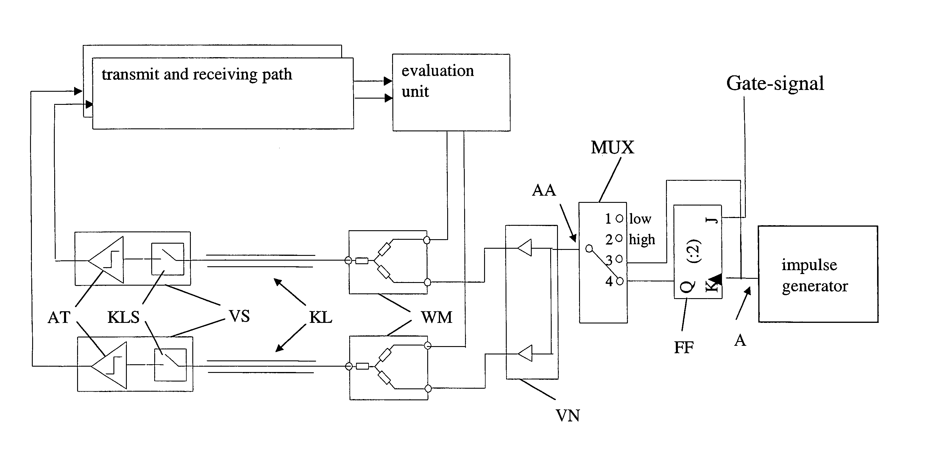
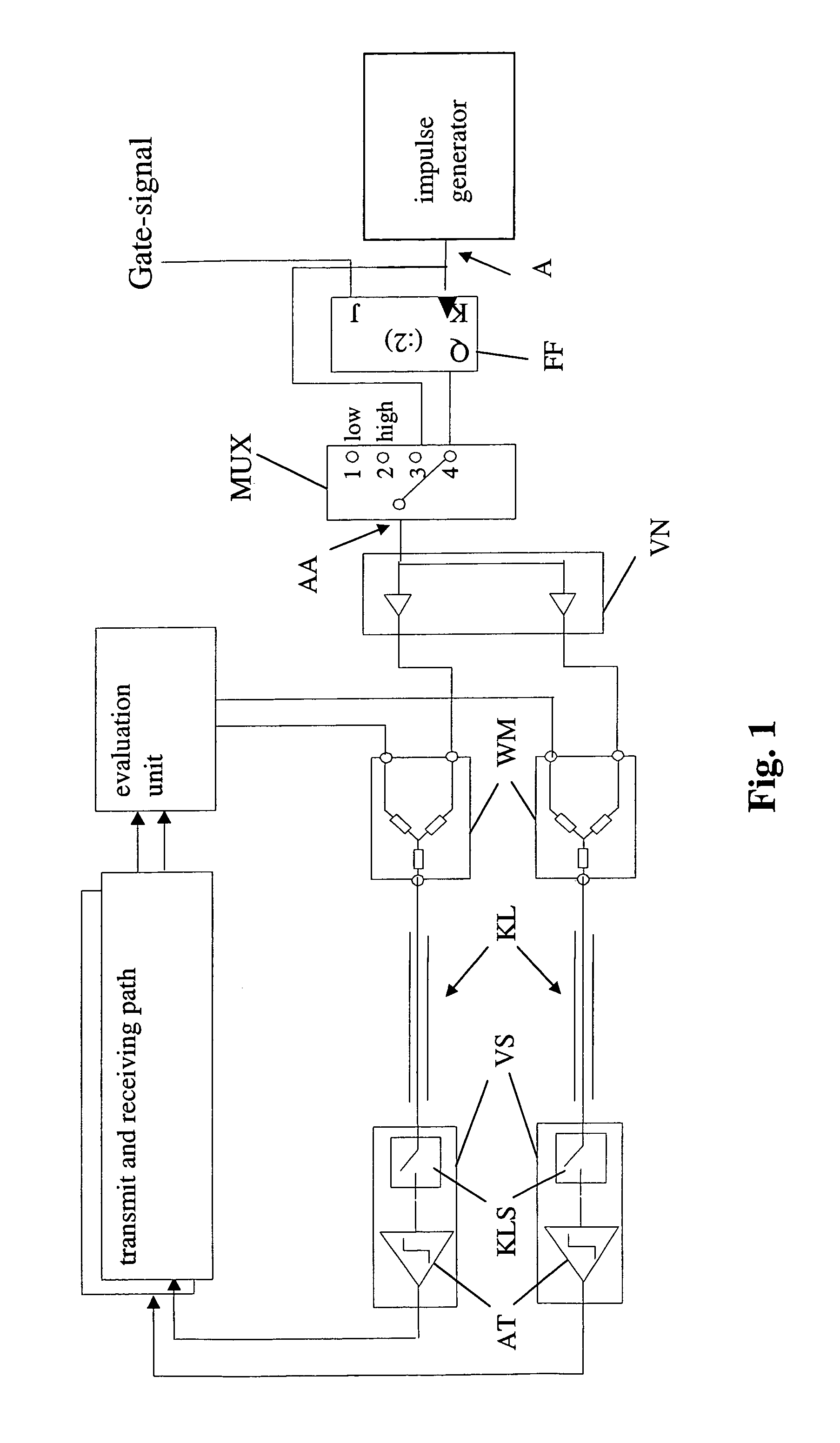
[0046]The exemplary circuit arrangement of a calibration circuit for implementing the method of the invention illustrated in FIG. 1 includes a timer TG that generates a base signal with a specifiable reference timer pulse by means of an integral so-called clock divider. The output A of the timer TG is connected to the input K of a J / K flip-flop FF. The J / K flip-flop is a so-called controlled 2 / 1 frequency divider. Consequently it is possible with the flip-flop that is used to generate precisely equal pulses without having to undertake further adjusting operations on the generated pulses. Hence, it is guaranteed that all pulses are of equal length. Instead of a J / K flip-flop FF, however, a so-called delay line and a Schmitt trigger gate can also be used. A control signal (gate signal) is positioned at the other input J of the J / K flip-flop FF.

[0047]The output Q of the J / K flip-flop FF is connected to an input 4 of a multiple alternation switch MUX that is connected downstream in seri...


PUM


Abstract

The invention concerns a method for generating calibration signals for calibrating spatially remote signal branches of antenna systems. In accordance with the invention, a base signal is generated by mean of a timer and is fed to a distributor unit for distribution of the base signal to amplifier circuits on the signal distribution lines respectively allocated to them. At the output of the amplifier circuits, a calibration signal is generated respectively via amplification of the base signal within a specifiable upper amplitude limit and a specifiable lower amplitude limit, which is fed to the respective feed-in point of the signal branch to be calibrated that is allocated to an amplifier circuit.

Description

CROSS-REFERENCE TO RELATED APPLICATIONS[0001]This application claims the priority of German application 103 01 125.0, filed Jan. 14, 2003, the disclosure of which is expressly incorporated by reference herein.BACKGROUND OF THE INVENTION[0002]The invention concerns a method for generating calibration signals for calibrating spatially remote signal branches of antenna systems.[0003]In calibrating signal branches of antenna systems, the calibration signals are usually centrally generated with the corresponding frequency at which the calibration should be conducted. Here it is problematic that the distributor lines have a dispersive behavior over the frequency. That is, the signal transit times are frequency and temperature-dependent, wherein the dependency is greater the higher the absolute frequency. Moreover a signal line has varying damping as a function of frequency, temperature, bending radius of the lines, and age.[0004]Due to imprecise adaptations to impedance, standing waves ar...

Claims


Application Information

Patent Timeline
IPC IPC(8): G01S7/40H01Q3/22H01Q3/26
CPCH01Q3/267
Inventor SCHUSTER, MANFREDHERRMANN, FRANZ
Owner AIRBUS DEFENCE & SPACE
Why Eureka
Try Eureka