Method to determine TDC in an internal combustion engine

a technology of internal combustion engine and tdc, which is applied in the direction of electric control, ignition automatic control, instruments, etc., can solve the problems of negative influence on the working life of the combustion engine, difficult measurement, and calculation of work output, so as to achieve effective management of the engine under operation, effective development of new ideas, and determination more accurately

Inactive Publication Date: 2006-10-03
ABB (SCHWEIZ) AG
View PDF13 Cites 24 Cited by
  • Summary
  • Abstract
  • Description
  • Claims
  • Application Information

AI Technical Summary

Benefits of technology

[0019]The main advantage of the invention is that TDC is determined more accurately with a method and apparatus that is also economic to apply. This means that sophisticated engine diagnostics, control and regulation may be applied to smaller, less expensive engines and not only engines in larger installations such as generators. These benefits can be gained both by more effective development of new or improved engines and from more effective management of engines under operation. The invention consequently offers significant environmental benefits due to reduced fuel consumption and emissions with reduced environmental impact without high investment in engine technology or measurement costs.
[0020]Another advantage of one embodiment of the invention is that only one input is required, an input dependent on gas pressure in a cylinder, in order to calculate IMEP according to the invention. Thus with fewer components the system is potentially less prone to breakdowns. In addition, a TDC position of the piston in a cylinder of an internal combustion engine is determined with greater accuracy than existing methods. It is also advantageous that another embodiment of the invention provides a means for determining crank angle that is independent of measurement of the flywheel angle.
[0021]The invention may be applied very widely to any motor, old or new, that can be fitted with a sensor for gas pressure for at least one cylinder. In an advantageous embodiment, the invention may be used to provide an input for an engine control or management device or system so that the engine can be monitored and / or regulated. The calculation elements of the method may be carried out by one or more inexpensive electronic components installed in a vehicle such that the results may advantageously be used to control fuel economy and exhaust emission quality.BRIEF DESCRIPTION OF THE FIGURES
[0022]A more complete understanding of the method and apparatus of the present invention may be had by reference to the following detailed description when taken in conjunction with the accompanying drawings wherein:
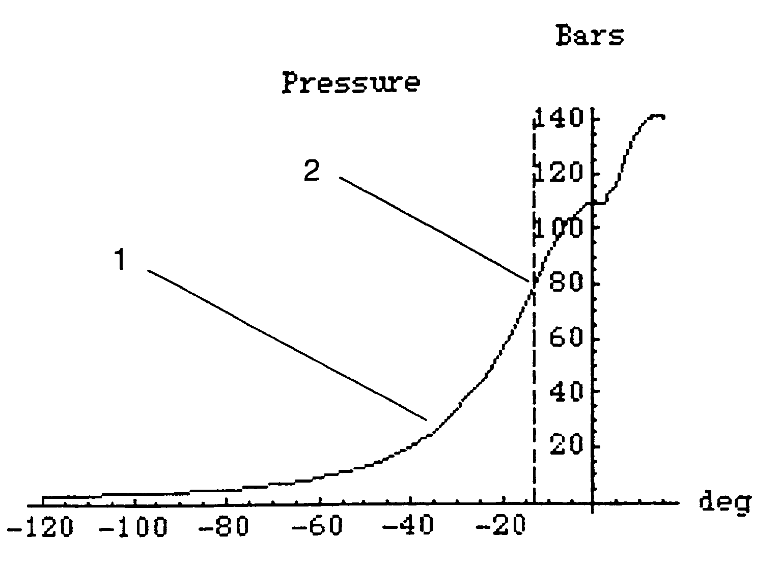
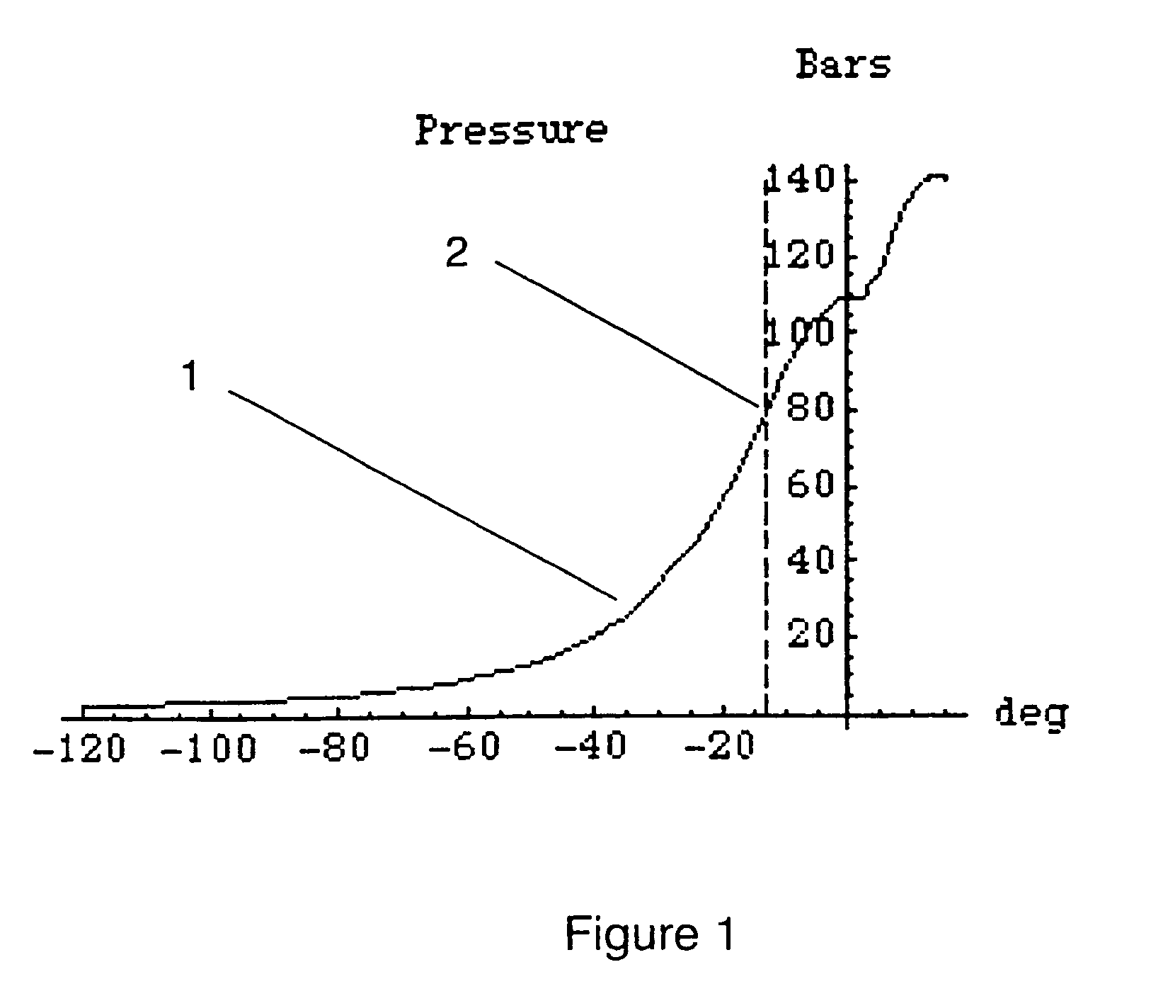
[0023]FIG. 1 shows a schematic curve of a relation between gas pressure in a cylinder and crank angle for a method according to an embodiment of the present invention;
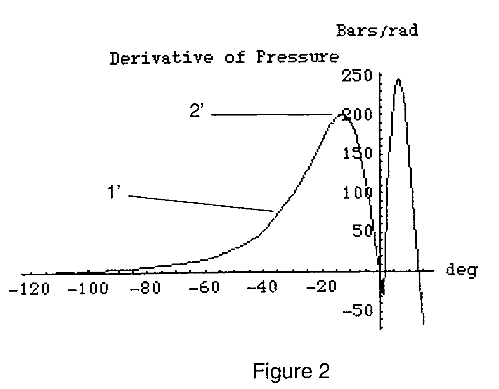
[0024]FIG. 2 shows a schematic curve of derivative of a relation between gas pressure in a cylinder and crank angle according to an

Problems solved by technology

Misfiring influences exhaust gas chemical composition and can also negatively influence the working life of a combustion engine.
A difficulty in the calculation of work output, IMEP of a cylinder is to determine accurately a crank angle for a piston together with the pressure corresponding to that crank angle.
Generally crank angle of a given piston is calculated from a measurement of the angular position of the crankshaft of the engine (crankshaft angle), as it is difficult to measure the piston position directly in the cylinder during operation.
A principal disadvantage with both of these methods is that they do not provide for determination of TDC in a motor under normal operation.
What is difficult in practice with most methods described is to determine accurately an angular offset that usually exists between the flywheel angle and the piston crank angle at a given moment in a revolution.
In addition in an engine under operation the dynamic interplay of stresses on components, free play clearances between mechanically connected components, friction and inertia of components means that the mechanical distances and relationships between components under operation may not be the same as distances and relationships between the same components at rest.

Method used


Image

  • Method to determine TDC in an internal combustion engine
  • Method to determine TDC in an internal combustion engine
  • Method to determine TDC in an internal combustion engine

Examples


Embodiment Construction

[0027]In order to determine a Top Dead Centre position of the piston in a cylinder the present invention comprises a method for determining a point of inflection in a curve dependent on a measurement of cylinder pressure related to crank angle. That is, the point in the pressure curve at which a derivative of the pressure curve in relation to crank angle is at a maximum or equivalent, and where a second derivative of the pressure curve is equal to zero.

[0028]FIG. 1 shows a schematic graph of a curve 1 for measured cylinder pressure on the y-axis plotted against crank angle in degrees on the x-axis. A first point of inflection 2 may be seen at about −13° on the curve.

[0029]The position of that point α (in radians) may be determined theoretically with the help of a fairly complicated formula as follows:

[0030]⁢α=-4(1+λ)⁢(1+2⁢(γ-0.0217))⁢(rc-1)+43⁢(-1-3⁢λ+3⁢λ2)⁢(5+4⁢(γ-0.0217))(1+λ)2⁢(1+2⁢(γ-0.0217))3⁢(rc-1)2

where[0031]λ=Relation between crank radius and piston connecting rod length.[00...


PUM


Abstract

A method and apparatus for accurately determining TDC in a cylinder of an internal combustion engine. Gas pressure is measured in the cylinder relative to crank angle, giving rise to a curve of gas pressure with crank angle. An offset is found by first computing the angular position of an inflexion point of the compression pressure curve measured as a function of the crank angle, and then computing the offset as the difference between the angular position of a piston in the cylinder and a theoretical value for said angular position of the piston dependent on a known or measured flywheel angle. The value of TDC corrected by the offset is then used to calculate a value of work output such as the Indicated Mean Effective Pressure (IMEP) which may be used for diagnostic and / or control purposes.

Description

TECHNICAL AREA[0001]The present invention concerns the technical area of methods to calculate variables useful in performing diagnostics and control of a combustion engine, such as the Indicated Mean Effective Pressure (IMEP), and other variables which require that the crank angle of the piston in the cylinder is accurately known. In particular the invention concerns a method to determine accurately when a piston in a cylinder of an internal combustion engine is at top dead centre (TDC).TECHNICAL BACKGROUND[0002]Many methods exist for controlling operation of a combustion engine. In particular, measurements of pressure from one or more cylinders of an engine are commonly used as a basis for engine performance measurement, monitoring and for control of an engine.[0003]One area of use for continually measuring pressure sensors is in very large combustion engines which are operated at relatively low revolutions per minute. Such motors are used for example as ships engines and as statio...

Claims


Application Information

Patent Timeline
Patent Type & Authority Patents(United States)
IPC IPC(8): G01M15/08F02D45/00F02D13/02F02D35/00F02D35/02F02D41/40F02P5/15G01M15/06
CPCF02D35/0007F02D35/023F02D41/009G01M15/06F02D13/02F02D41/401F02D2200/0402F02P5/1504
Inventor SOBEL, JARL R.
Owner ABB (SCHWEIZ) AG
Why Eureka
Try Eureka