
Water supply system

a water supply system and water supply technology, applied in the direction of positive displacement liquid engines, pumping pumps, machines/engines, etc., can solve the problem of relative cost of installation, and achieve the effect of preventing corrosion or contamination of water

Active Publication Date: 2006-10-10
HANSON DWIGHT EUGENE
View PDF10 Cites 1 Cited by
  • Summary
  • Abstract
  • Description
  • Claims
  • Application Information

AI Technical Summary

Benefits of technology

[0009]It is a still further object of the invention to provide a novel water supply system that is economical to install.
[0010]It is a still further object of the invention to provide a water supply system that is economical and convenient to maintain and use.
[0011]It is a still further object of the invention to provide an economical water supply system.
[0012]In accordance with the above and further objects of the invention, a water supply system includes a water supply module that cooperates with a variable flow-rate pumping system to provide water from a well to a plumbing system such as a plumbing system of a building or a stand-alone water source in a park or the like. The variable flow rate pumping system can be any type such as a pump driven by a variable speed motor, the speed of which varies with an input signal related to water pressure or a constant speed motor driving a pump with the flow rate to the pressure tank being controlled by a cycle stop valve and a pressure switch that responds to pressure in the system. The water supply module includes a housing or casing, a pressure tank and a pressure sensor or cycle stop valve connected to maintain pressure in the system by supplying water to the pressure tank at a higher rate when demand is greater. The casing of the water supply module is larger than the size of the well casing by more than a nominal size and is sufficiently large to receive the pressure tank within it. The drop tube extends through an opening in a bottom-closing member into the well casing. The closing member is required because of the larger size of the housing but may have the disadvantage of receiving condensation. Preferably some measures are taken to avoid rust and corrosion from moisture in the water supply module.
[0014]To prevent corrosion or contamination of the water from drainage in the water supply module, the water supply module: (1) is closed to prevent water from outside the module from entering the module; and (2) the water supply module includes a suitable means for removing water caused by condensation or leakage such as for example a desiccant or a sloped bottom member which may permit collection of moisture and drainage into the well and may be made of special materials to prevent rust and growths from occurring in the inside of the housing for the water supply module. The top of the module is closed by a cover to prevent contaminants from entering the housing and being carried into the well with moisture.
[0016]As can be understood from the above description, the water supply system of this invention has several advantages, such as: (1) it can be easily installed from the top of the well; (2) it can be easily maintained because the parts are easily removable through the top of the well or the well casing; and (3) it is economical in construction, installation and maintenance.

Problems solved by technology

This arrangement has a serious disadvantage in that the pit accumulates waste water and the like and may permit contaminants to drain into the well.
This type of prior art water supply module has several disadvantages such as for example: (1) the size of pressure tank needed to satisfy demand for some plumbing systems is relatively large; (2) a separate building or space in the building receiving water from the well or other underground opening is needed for the pressure tank; and (3) they are relatively expensive to install, under some circumstances, because the pressure tank is located or housed at a location spaced from the well.

Method used


Image

  • Water supply system
  • Water supply system
  • Water supply system

Examples


Embodiment Construction

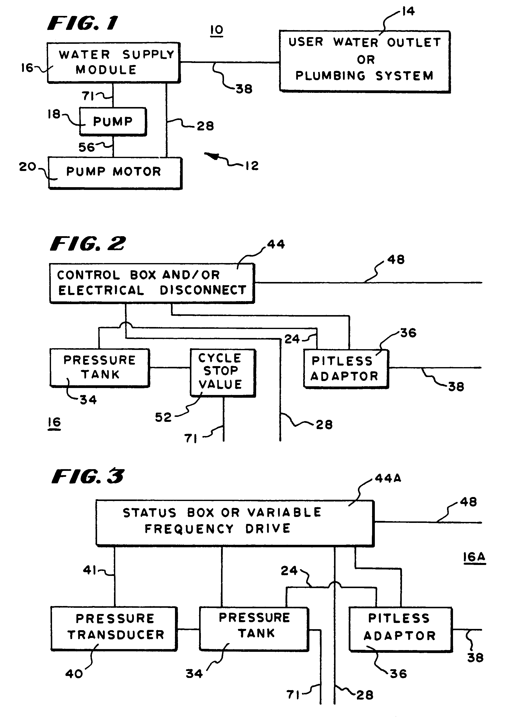
[0031]In FIG. 1, there is shown a block diagram of a water supply system 10 having a pumping station 12 and a plumbing system 14. The pumping station 12 is principally located within a well casing and supplies water through one or more conduits 38 to the user water outlet or plumbing system 14. The plumbing system 14 may be that of a household or a separate stand-alone outlet or the plumbing system of a large building or any other facility requiring water.

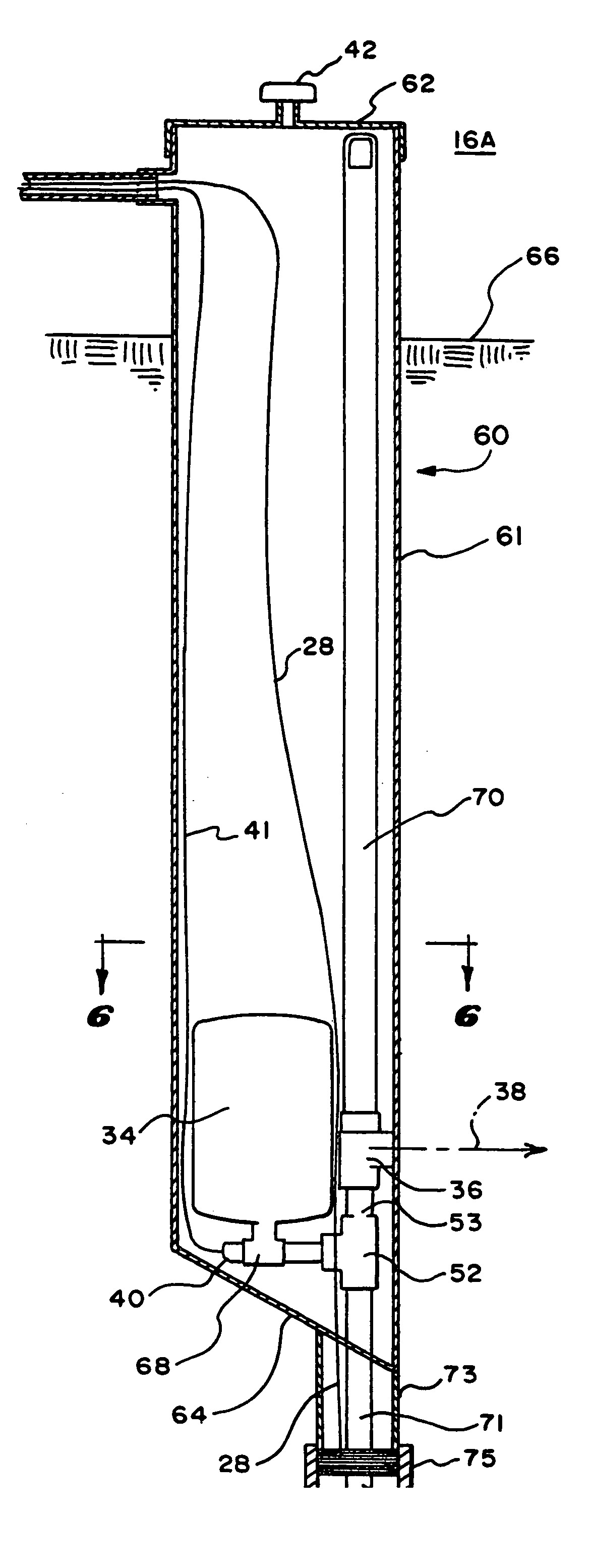
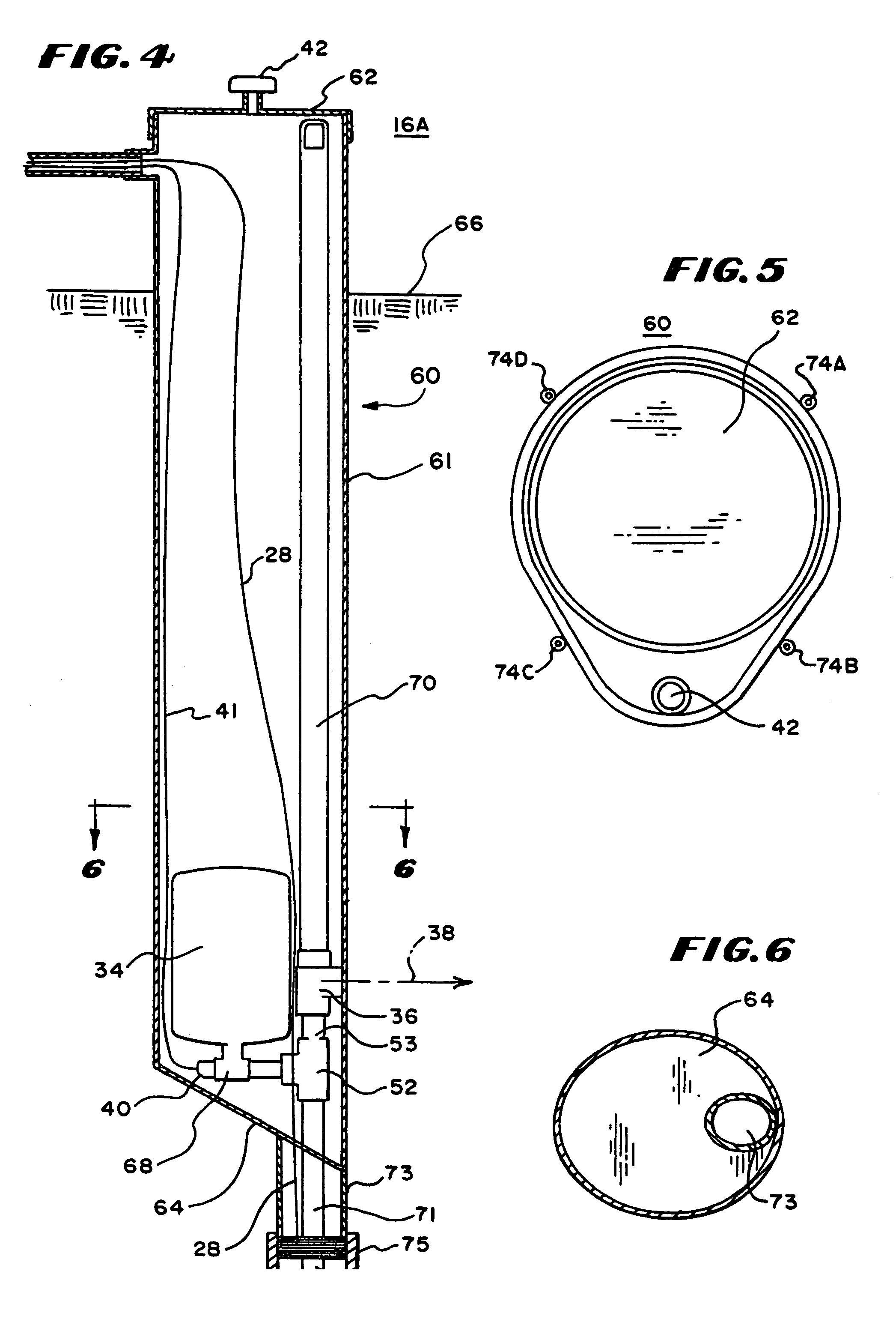
[0032]The pumping station 12 includes a water supply module 16, a pump 18 and a pump motor 20. The pump 18 and pump motor 20 are submersible and are within the liquid in the well casing to pump water upwardly to the water supply module16. The water supply module 16 includes the pressure tank, the pitless adapter or pitless unit, and may include gages, control boxes, status boxes, transducers and the like. While the water supply module 16 is shown in FIG. 1 as a separate integrated unit separate from the pump 18 and the pump motor 2...


PUM


Abstract

A water supply system has its housing and pressure tank sized so that the pressure tank fits within the housing, thus avoiding the need for another separate opening in the ground for the pressure tank. With this arrangement, there is less work in installation of the system and in maintaining the system. A control box for the system can be in the housing near the top where it is accessible or it can be separate. Preferably, the pump will be driven by a variable speed pump or a stop cycle valve will be used. Preferably, the pressure tank has a capacity of less than 40 gallons and the housing has an enlarged portion and a reduced portion with the pressure tank being mounted within said enlarged portion of said housing. The enlarged portion of the housing has an enlarged portion bottom surface and the reduced portion of said housing has a reduced portion bottom surface with the reduced portion of said housing being integrally formed with said enlarged portion bottom surface and extending downwardly therefrom and the conduit is adapted to be connected to a pumping system within a well casing and extends through the reduced portion bottom surface for supplying water to the pressure tank.

Description

RELATED CASES[0001]This case is a continuation in part of U.S. application Ser. No. 10 / 059,679 filed Jan. 30, 2002 now U.S. Pat. No. 6,592,342 in the name of Dwight Eugene Hanson.BACKGROUND OF THE INVENTION[0002]This invention relates to water supply systems.[0003]It is known in the water supply system art to have a pressurized water tank communicating with a well pipe through a submersible pump. In these systems, the pump is controlled by a sensing system to maintain pressure in the water system. The water may be supplied to households or to other plumbing or water systems.[0004]In one prior art water supply system of this type, the pressure tank and associated equipment are mounted in a pit. The well casing extends upwardly into the bottom of the pit and connected there to pipes leading to the pressure tank where access is available to the connection. This arrangement has a serious disadvantage in that the pit accumulates waste water and the like and may permit contaminants to dra...

Claims


Application Information

Patent Timeline
IPC IPC(8): F04B17/00E03B3/10E03B5/04E03B11/02F04D13/16
CPCE03B3/10E03B5/04E03B11/02F04D13/16Y02A20/00
Inventor HANSON, DWIGHT EUGENE
Owner HANSON DWIGHT EUGENE
Learn More