Cylindrical electron beam generating/triggering device and method for generation of electrons

a technology of generating/triggering device and electron beam, which is applied in the direction of gas-filled discharge tubes, discharge tubes/lamp details, coatings, etc., can solve the problems of limited current density, short lifetime, and limited electron emission, so as to achieve effective electron emission, controllable intensity, and long lifetime

Active Publication Date: 2006-10-17
NEOCERA
View PDF6 Cites 231 Cited by
  • Summary
  • Abstract
  • Description
  • Claims
  • Application Information

AI Technical Summary

Benefits of technology

[0012]It is an object of the present invention to provide a surface discharge device for electron beam generation, as well as for discharge triggering to create a sufficient condition for ignition of a pulse discharge for the generation of electrons. Such a device has a controllable intensity of the discharge, long lifetime, and an effective electron emission.

Problems solved by technology

Direct extraction of electrons from a metal surface by applying an electric field, defined as an auto electron emission requires a high electric field and is known to be limited in the current density.
Disadvantages of such a trigger of the discharge ignition are (1) limited emission of electrons and (2) short lifetime.
Both of these disadvantages are related to the fact that current tends to flow through a narrow channel between metallic electrodes of the device.
As a result, volume of the plasma channel is limited, and accordingly so is the emitted electron current.
Additionally, due to the current confinement into the channel dielectric surface erosion limits lifetime of the trigger to as little as 106 pulses.
Third, due to the distributed nature of the discharge, erosion of the surface is reduced, and lifetime of such a device is elongated.
However, due to their distributed nature, the design is less effective for some devices where the generated electrons should be concentrated in narrow beams.

Method used


Image

  • Cylindrical electron beam generating/triggering device and method for generation of electrons
  • Cylindrical electron beam generating/triggering device and method for generation of electrons

Examples


Embodiment Construction

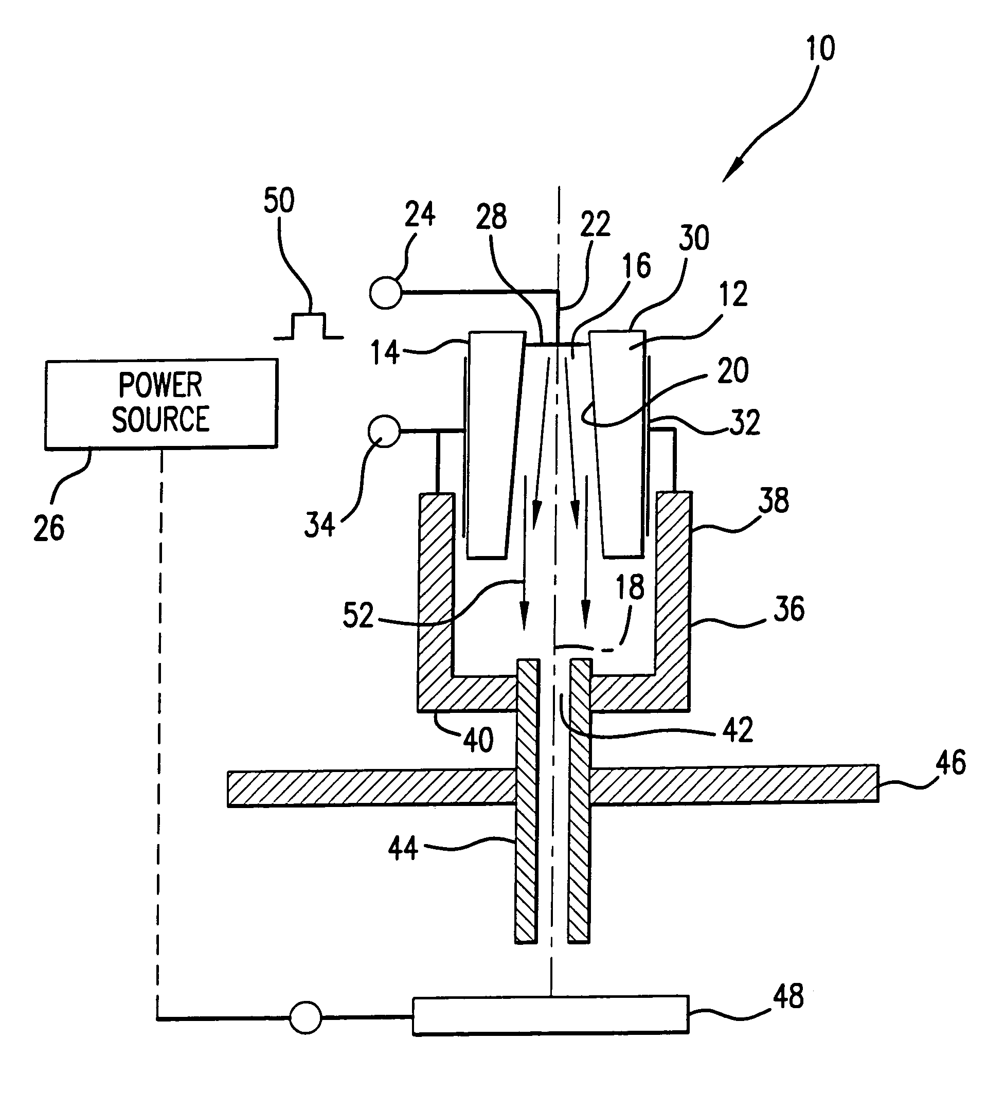
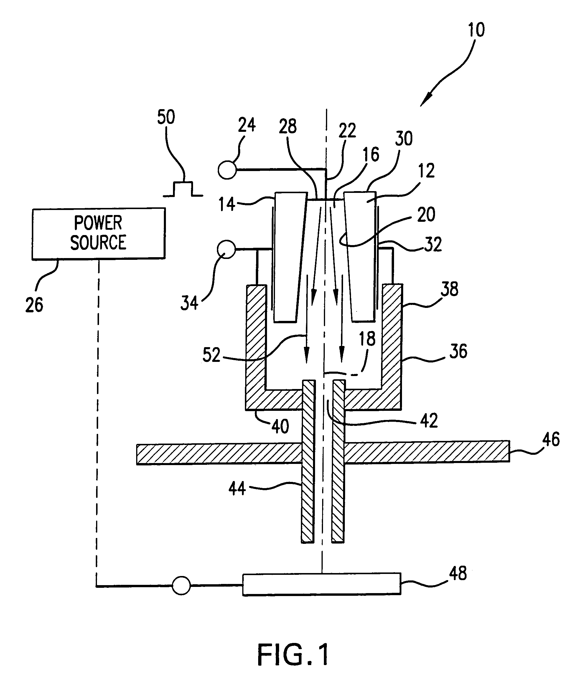
[0036]Referring to FIG. 1, the cylindrical surface discharge device 10 of the present invention includes a cylindrically contoured or cylinder shaped member 12 formed of a dielectric material with dielectric constant ε in excess of 100. The cylinder shaped member 12 has an external surface 14 and is formed with a central opening 16 extending longitudinally through the cylinder shaped member 12 along the axis of symmetry 18 thereof. The central opening 16 may be shaped as a cylinder or a cone. The surface of the central opening 16 defines an internal surface 20 of the cylinder shaped member 12. The diameter of the central opening 16 may range from 3 to 15 mm.

[0037]The cylindrical surface discharge device 10 further includes an internal electrode 22 having a terminal 24 connected to a power source 26 and an opposite end 28 positioned in contact with the cylinder shaped member 12 in proximity to the edge 30 thereof. Specifically, as shown in FIG. 1, the internal electrode 22 makes cont...


PUM

PropertyMeasurementUnit
diameteraaaaaaaaaa
dielectric constantaaaaaaaaaa
diameteraaaaaaaaaa

Abstract

A surface discharge device performing functions of a trigger and electron beam generator includes a cylinder shaped member formed from a dielectric material with dielectric constant ε>100, in which a central opening is formed having a conical or cylindrical shape. An internal electrode is electrically coupled to the internal surface of the cylinder shaped member. An external electrode covers the external surface of the cylinder shaped member. A triggering pulse is applied between the external and internal electrodes to generate emission of electrons in the central opening and formation of the conducting plasma to ignite the device and serve as a source of electrons for generating an electron beam. The conducting plasma charges a capacitor formed by the cylinder shaped dielectric member and the external electrode. The cylinder shaped member is positioned in a hollow cathode having a central bore hole in the bottom. An anode is positioned remotely from the cathode and an electric field exists dynamically in space between the cathode and anode for at least a portion of the duration of the triggering pulse.

Description

FIELD OF THE INVENTION[0001]The present invention relates to the generation of electrons and in particular to methods of generating spatial regions of high concentrations of electrons.[0002]More in particular, the present invention relates to a technique for generation of initial electrons in pulsed discharge devices with a restricted discharge of cylindrical geometry as for example, in pseudo-spark switches, channel spark discharge devices, etc.[0003]Specifically, the present invention relates to a cylindrical surface discharge device designed to fulfill two functions in combination, such as triggering of the generation of electrons and for generating the electrons, in the form of electron beams. Viewed as a trigger, such a device provides sufficient conditions for a pulse discharge device to ignite. When viewed as a generator, the device creates electron discharge, and to some extent controls the intensity of the discharge.[0004]Further, the present invention relates to a cathode ...

Claims


Application Information

Patent Timeline
Patent Type & Authority Patents(United States)
IPC IPC(8): H01J17/26H01J61/28H01J3/02
CPCH01J3/025
Inventor STRIKOVSKI, MIKHAIL
Owner NEOCERA
Why Eureka
Try Eureka