Self-biased comparator with hysteresis control for power supply monitoring and method

a technology of power supply monitoring and comparator, which is applied in the direction of pulse manipulation, pulse technique, instruments, etc., can solve the problems of i/o cell latch-up and/or permanent damage, damage to the integrated circuit, and additional cost of such translation buffer circuit us

Inactive Publication Date: 2006-10-17
TEXAS INSTR INC
View PDF4 Cites 14 Cited by
  • Summary
  • Abstract
  • Description
  • Claims
  • Application Information

AI Technical Summary

Benefits of technology

[0025]In one embodiment, a CMOS integrated circuit avoids forward biasing of parasitic PN junctions by using th...

Problems solved by technology

However, use of such translation buffer circuits involves additional cost.
The forward-biasing of parasitic junction diode D1 will not only conduct a large amount of current through it but it may also cause latch-up and/or permanent damage to the I/O cell.
The resulting high current may damage the integrated circuit.
If the foregoing power-up and power-down sequences are not observed, parasitic junction diode D2 will become forward-biased, causing it to conduct a large amount of current through the diode D2, and may also cause latch-up and/or permanent damage to I/O cell 10.
The foregoing restriction on the power-up sequence and power-down sequence of the analog and digital power supply voltages limits the convenience of using ...

Method used


Image

  • Self-biased comparator with hysteresis control for power supply monitoring and method
  • Self-biased comparator with hysteresis control for power supply monitoring and method
  • Self-biased comparator with hysteresis control for power supply monitoring and method

Examples


Embodiment Construction

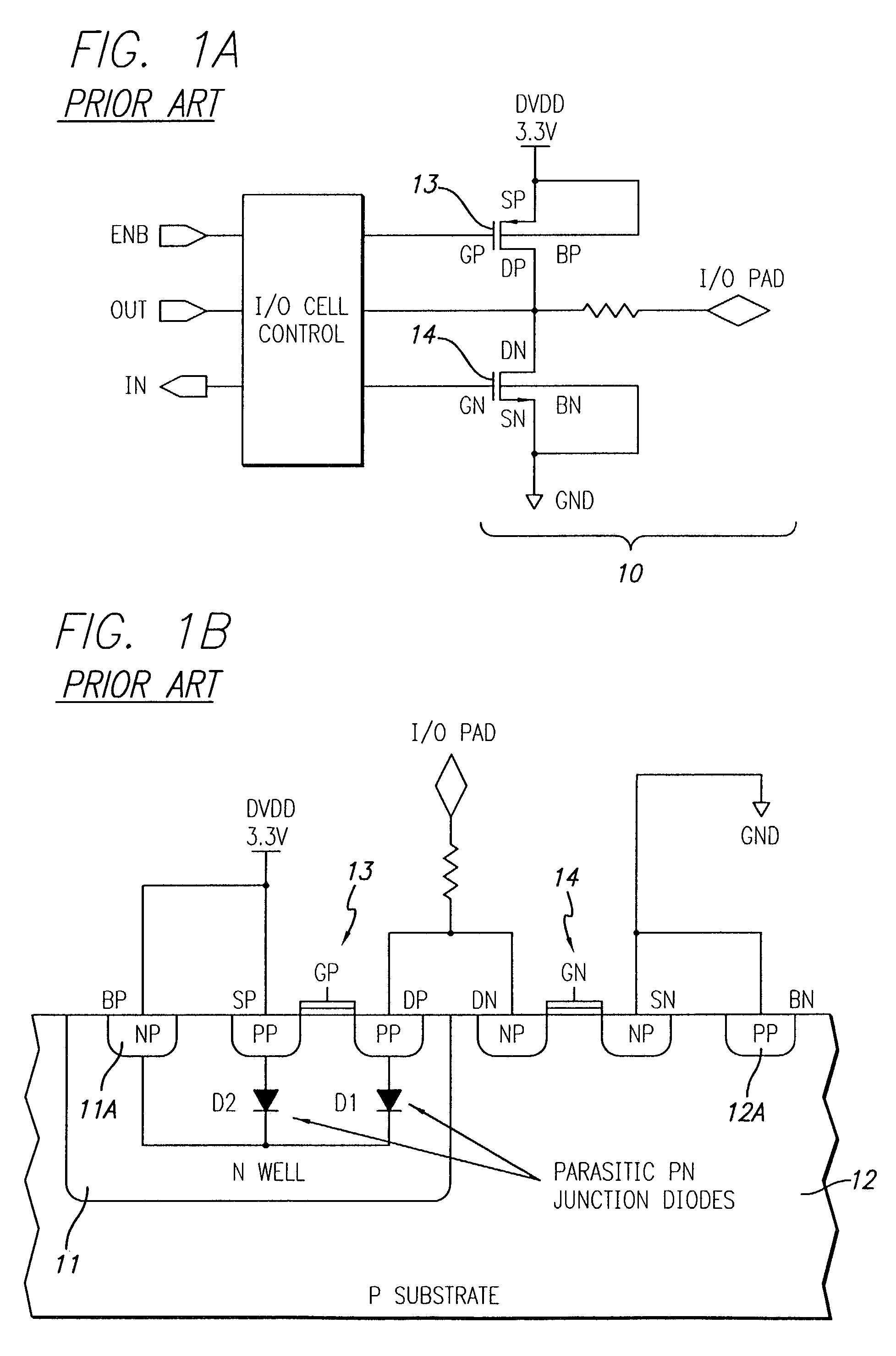
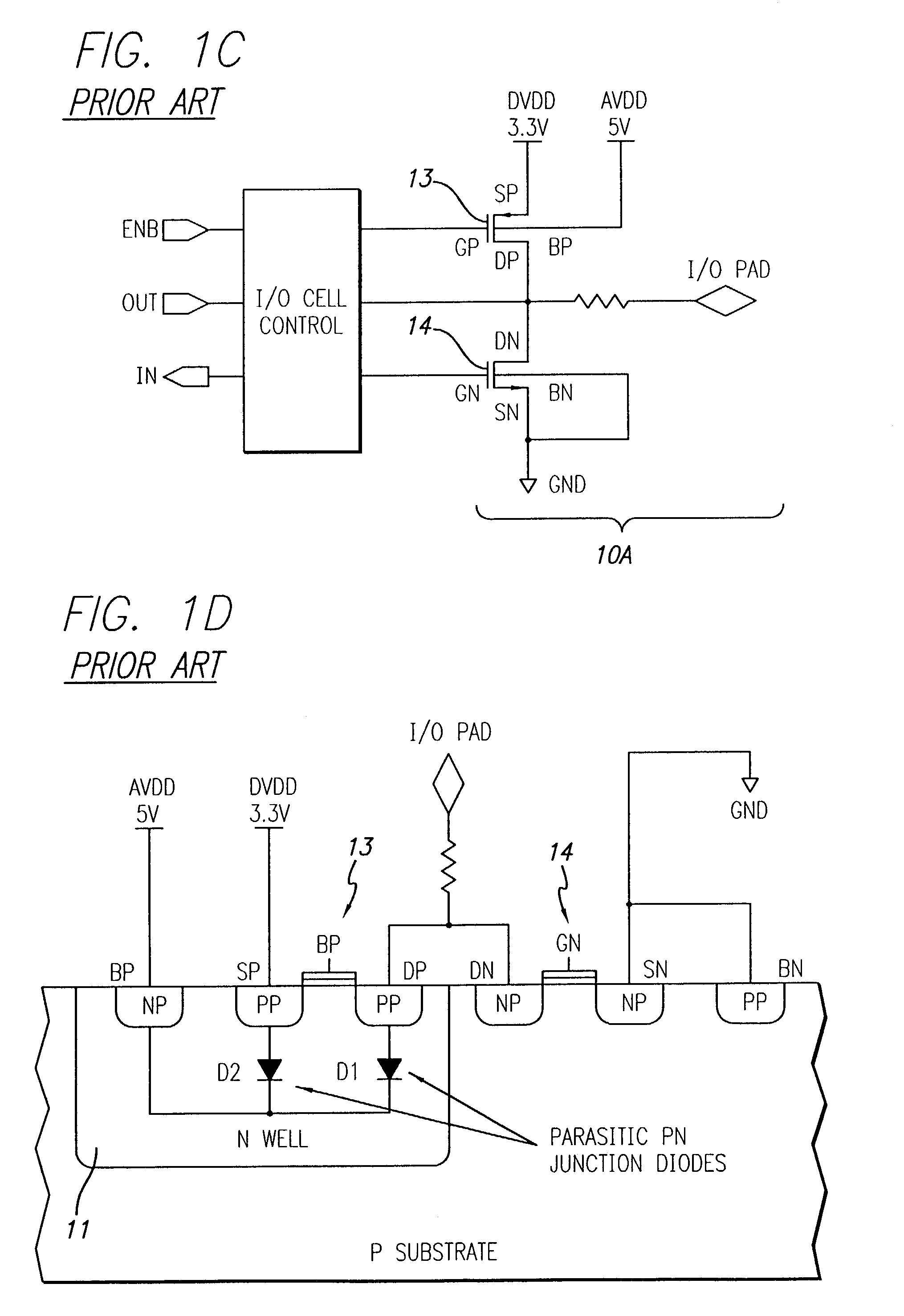
[0041]The invention provides several new self-biased comparator circuits and several supply voltage monitor circuits that include any of the new comparator circuits. The new supply voltage monitor circuits are utilized to bias a N-type well region of an integrated circuit to prevent forward biasing of parasitic PN junctions during power-up sequencing of multiple power supply voltages connected to the integrated circuit.

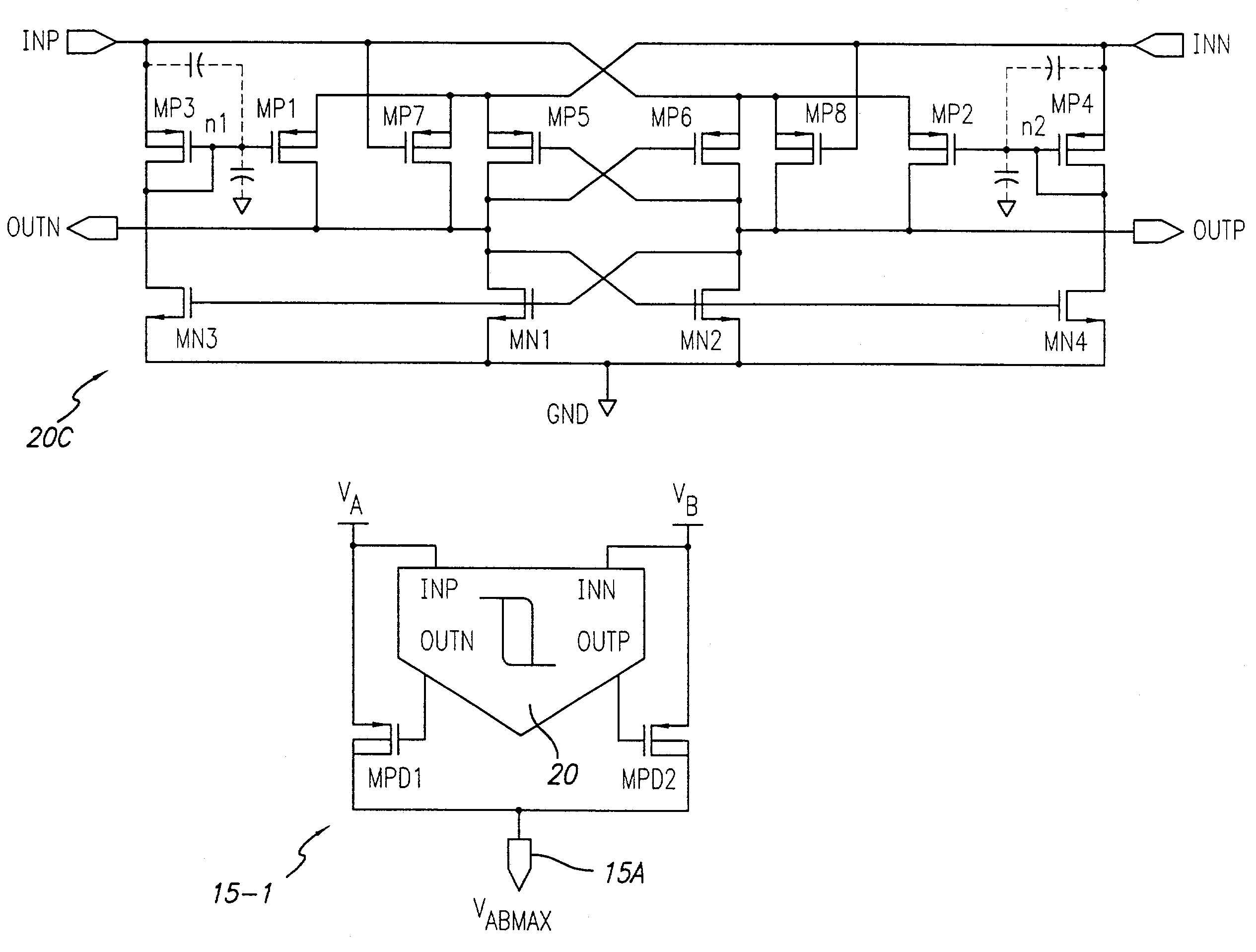
[0042]FIG. 4 shows a basic self-biased comparator circuit 20A, and FIGS. 5 and 6 show modified versions 20B and 20C, respectively, of the basic comparator 20A with additional features. FIG. 7 shows a supply voltage monitor circuit 15-1 that includes any of the comparators of FIGS. 4–6 and functions to select the higher of two supply voltages VA and VB and applies the higher of the two supply voltages via conductor 15A as an output voltage VABMAX to be used to bias an N-type well region. FIG. 8 shows the supply voltage monitor circuit 15-1 of FIG. 7 with its output vol...


PUM


Abstract

A voltage monitor circuit for biasing a well region of a CMOS circuit includes a self-biased comparator which compares first (INP) and second (INN) input signals. The comparator includes first (MN1) and second (MN2) N-channel transistors with grounded sources, a drain of the first N-channel transistor and a gate of the second N-channel transistor being coupled to a first output (OUTN), and a drain of the second N-channel transistor and a gate of the first N-channel transistor being coupled to a second output (OUTP). First (MP1) and second (MP2) P-channel transistors are operated to couple the second or first input signal to the second or first output, respectively, by controlling the gate-to-source voltage of the first or second P-channel transistor according to the polarity of a voltage difference between the first and second input signals.

Description

BACKGROUND OF THE INVENTION[0001]The present invention relates generally to supply voltage monitoring circuits for use in detecting that of two supply voltages is higher in an integrated circuit containing circuitry which otherwise can be damaged if the two supply voltages are increased or “powered up” in the wrong sequence. More particularly, the invention relates to monitoring and switching circuitry that automatically connects the N-type well regions of P-channel transistors to the higher of the two or more supply voltages.[0002]In a mixed-signal system, i.e., a system including both digital signals and analog signals, it is common for the associated digital circuitry and analog circuitry to be powered by separate power supply voltage sources having different voltage levels, for example 5 volts for the analog circuitry and 3.3 volts for the digital circuitry. However, often the digital circuitry that interfaces with the mixed-signal system is powered by a 5 volt supply voltage. T...

Claims


Application Information

Patent Timeline
IPC IPC(8): H03K5/22H03K3/356H03K3/3565H03K5/24
CPCH03K3/356113H03K3/3565H03K5/2472
Inventor WANG, BINANSTULIK, PAUL
Owner TEXAS INSTR INC
Why Eureka
Try Eureka