Image display apparatus

a technology of image display and display apparatus, which is applied in the field of high-resolution imaging image display apparatus, can solve the problems of insufficient resolution and sharpness, inconvenient operation, and inconvenient operation, and achieve the effects of reducing the relative optical intensity near the edge of the pixel, reducing the pixel sharpness, and reducing the relative optical intensity

Active Publication Date: 2006-10-24
RICOH KK
View PDF27 Cites 14 Cited by
  • Summary
  • Abstract
  • Description
  • Claims
  • Application Information

AI Technical Summary

Benefits of technology

[0061]According to the present invention, the relative optical intensity near the edge of the pixel can be decreased according to the pixel profile of the non-rectangle configuration, the influence of the lap between the contiguity pixels when carrying out the optical-axis shift is reduced, and it is possible to provide an image display apparatus which realizes the “sharpness” of the image and the “smoothness of the field and the edge” simultaneously.
[0062]Moreover, the angle of the outgoing light ray can be reduced by increasing the relative value to the pixel pitch for the full width at half maximum of the pixel profile, a

Problems solved by technology

However, as the evaluation by viewing, the “hardness”, the “jaggies”, and the “image discontinuity” of the image become conspicuous.
The problem corresponds to the disadvantage of the image of the liquid crystal over the image of CRT.
However, the “resolution” and the “sharpness” are not so good for the number of the pixels or on the basis of the number of the pixels.
When the 4-fold high-resolution imaging is performed and pixel reduction is carried out to 50% or less of the conventional rates of the linear aperture (or the usual rate of the area-aperture is 25% of the 2's power), the pixel configuration of the projection image of projecting the reduced pixel with the projection lens is difficult to realize the “smoothness of the field and the edge” which is demanded in the case of the high resolution, unlike the case of the conventional projector of low resolution.
When MTF of the projection lens becomes still smaller than 30%, the inclination becomes still larger, improvement in the image quality when performing high-resolution imaging by carrying out the optical-axis shift in the case is almost lost, and it becomes impossible to display only the deteri

Method used


Image

  • Image display apparatus
  • Image display apparatus
  • Image display apparatus

Examples


embodiment 1

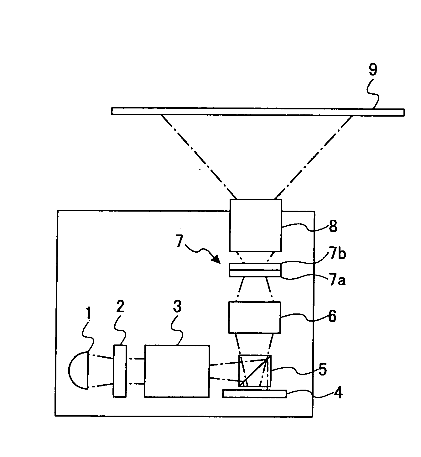
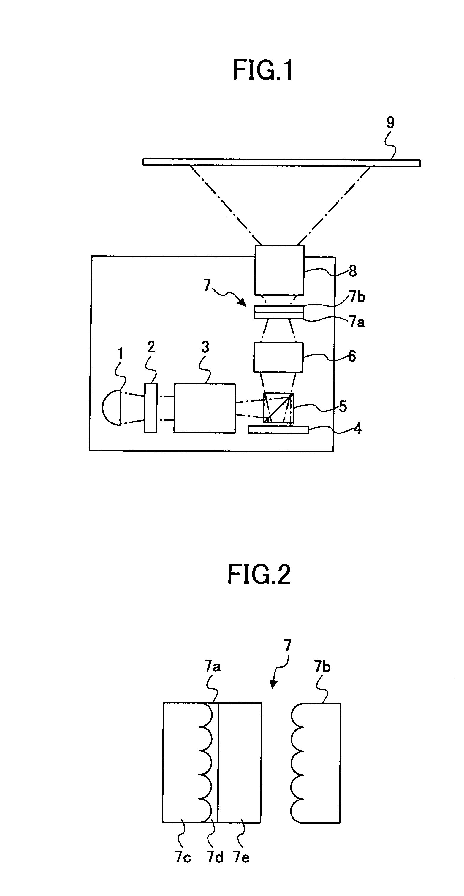
[0098]FIG. 1 and FIG. 2 show a projection image display apparatus according to the present invention.

[0099]Specifically, FIG. 1 shows the projection image display apparatus of the embodiment and FIG. 2 shows an example of the pixel reduction unit.

[0100]In FIG. 1, reference numeral 1 is a white light source including a high-pressure mercury lamp with the reflector, 2 is an optical integrator, such as the fly eye lens, 3 is a color separation unit, such as a color wheel, 4 is a spatial optical modulator, 5 is a polarization beam splitter (PBS), 6 is a macro lens, 7 is a pixel-profile deformation unit including a first micro-lens array 7a and a second micro-lens array 7b, 8 is a projection lens, and 9 is a screen.

[0101]Although not illustrated in FIG. 1, an optical-axis shift unit is provided in the projection lens 8 at the side of the pixel-profile deformation unit, the optical-axis shift unit using the liquid crystal cell having the perpendicular orientation of the ferrodielectric li...

embodiment 2

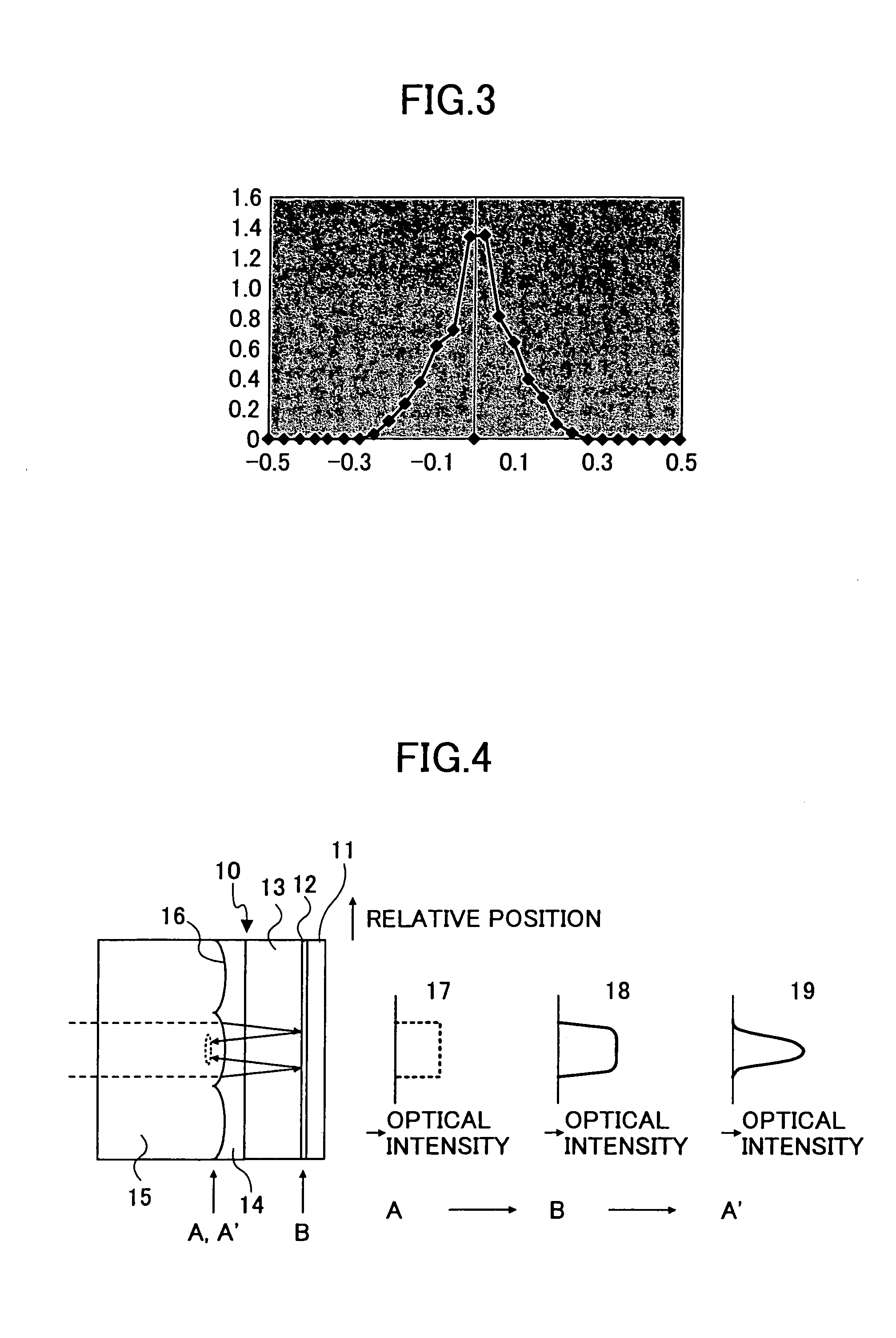
[0153]FIG. 4 shows the composition of the embodiment 2 which united the pixel-profile deformation unit 10 of the present invention with LCOS.

[0154]In FIG. 4, reference numeral 11 is the silicon substrate, 12 is the liquid crystal layer, 13 is the middle substrate, 14 is the adhesive layer, 15 is the micro-lens substrate, 16 is the convex configuration formed on the micro lens substrate, and 17, 18 and 19 are the optical intensity distributions of the light ray which is equivalent to the pixel profile at the locations A, B and A′ as indicated in FIG. 4.

[0155]In FIG. 4, it is the back plain of LCOS, and the active unit and reflector by CMOS are formed in the silicon substrate 11 for every pixel, and the reflection-type spatial optical modulation in the pixel unit can be performed to it using the polarization lighting light and polarization separation means by the liquid crystal layer 12 by impressing the electric field to the liquid crystal layer 12 included by the middle substrate 13...

embodiment 3

[0212]The comprehensive result when forming the projection image for evaluation by calculation and the experiment, and carrying out subjectivity evaluation is shown in Table 1 like the FIG. 5 of the

[0213]The projection image for evaluation is evaluated, after also changing the location and characteristics of the projection lens and optimizing, while changing the optical characteristics of the pixel-profile deformation unit.

[0214]

TABLE 1CTFSkirt IntensityHalf-Width (%)(%)(%)3040506070803054DEDEED4043DCBBBD5033BBAAAD8011BEAEAD


PUM


Abstract

An image display apparatus includes an indicating element which modulates or emits light as a pixel in accordance with image information. A displacement unit optically displaces a position of the pixel for each of two or more sub-fields constituting an image field corresponding to the image information. A projection unit enlarges the pixel and projects an enlarged pixel on a screen. A pixel-profile deformation unit changes an optical intensity profile of the pixel.

Description

BACKGROUND OF THE INVENTION[0001]1. Field of the Invention[0002]The present invention relates to an image display apparatus of high resolution imaging which is provided with a pixel displacement unit which carries out optical displacement of the pixels of the imaging elements, such as those in a spatial optical modulator or a spatial light discharge unit, for each of two or more sub-fields of the image field. More specifically, the present invention relates to a projection image display apparatus of high resolution imaging which is applicable to a front or rear projector which projects a real image on the screen, and a head-mounted display or a view finder which projects a virtual image on the screen.[0003]2. Description of the Related Art[0004]Japanese Laid-Open Patent Application No. 04-113308. (Japanese Patent No. 293926), Japanese Laid-Open Patent Application No. 05-289044, Japanese Laid-Open Patent Application No. 09-152572, Japanese Laid-Open Patent Application No. 06-324320, ...

Claims


Application Information

Patent Timeline
IPC IPC(8): G03B21/28G02B27/10G02B27/44G02B5/18G02F1/00G02F1/1335H04N5/74
CPCH04N5/7416H04N9/3188
Inventor MIYAGAKI, KAZUYAKAMEYAMA, KENJIOSAKA, TAKANOBUKATOH, IKUOTAKAURA, ATSUSHINAMIE, KENJITAKIGUCHI, YASUYUKI
Owner RICOH KK
Why Eureka
Try Eureka