Downhole high resolution NMR spectroscopy with polarization enhancement

a high-resolution, nmr-based technology, applied in the direction of nmr measurement, borehole/well accessories, instruments, etc., can solve the problems of deleterious changes, limited sample material extractable from a limited number, and associated technical and practical limitations, so as to enhance the polarization of the 13c nucleus, enhance the amplitude of the received 13c signal, and enhance the signal amplitude

Inactive Publication Date: 2006-10-24
BAKER HUGHES HLDG LLC
View PDF27 Cites 79 Cited by
  • Summary
  • Abstract
  • Description
  • Claims
  • Application Information

AI Technical Summary

Benefits of technology

[0015]In a first aspect the polarizing agent is responsive to electron spin resonance, i.e. it contains atoms or molecules with unpaired electrons. The mixture (here called the sample) of formation fluid and polarizing agent is transferred into the NMR / ESR probe that is in the magnet. In the magnet the sample is first magnetized to thermal equilibrium. By subjecting the sample to high frequency (HF), meeting the ESR resonance condition, and making use of the Overhauser effect (OE), the polarization of the 13C nuclei can be enhanced beyond equilibrium by a hyperpolarization factor of up to 2600 (theoretical maximum). Once the 13C nuclei are hyperpolarized any known 13C measurement can be executed by radiating the appropriate RF pulse sequence or by performing a CW NMR measurement at the 13C resonance frequency. The amplitude of the received 13C signals will be enhanced by the hyperpolarization factor. A description of the Overhauser Effect and also of the Nuclear Overhauser Effect is found in the monograph of C. P. Slichter, “Principles of Magnetic Resonance”, 3rd enlarged and updated edition 1990.

Problems solved by technology

A number of technical and practical limitations are associated with this approach.
Such limitations include the limited sample material extractable from a limited number of downhole locations.
Reversible changes are deleterious because they occur slowly and therefore impact sample handling and measurement efficiency.
Furthermore, since fluid analysis laboratories are frequently distant from the well site, there are substantial delays—often several weeks—in obtaining results.
If a sample is for some reason corrupted or lost during sampling, transportation, or measurement, there is no possibility of returning to the well to replace it.
This results in gradual loss of phase coherence of the magnetic moments and hence in a loss of macroscopic magnetization and hence in a loss of NMR signal.
It is not possible to generate a highly homogeneous magnetic field inside the earth formation.
These magnetic field properties allow chemical shift NMR analysis, not feasible in the formation in situ.

Method used


Image

  • Downhole high resolution NMR spectroscopy with polarization enhancement
  • Downhole high resolution NMR spectroscopy with polarization enhancement
  • Downhole high resolution NMR spectroscopy with polarization enhancement

Examples


Embodiment Construction

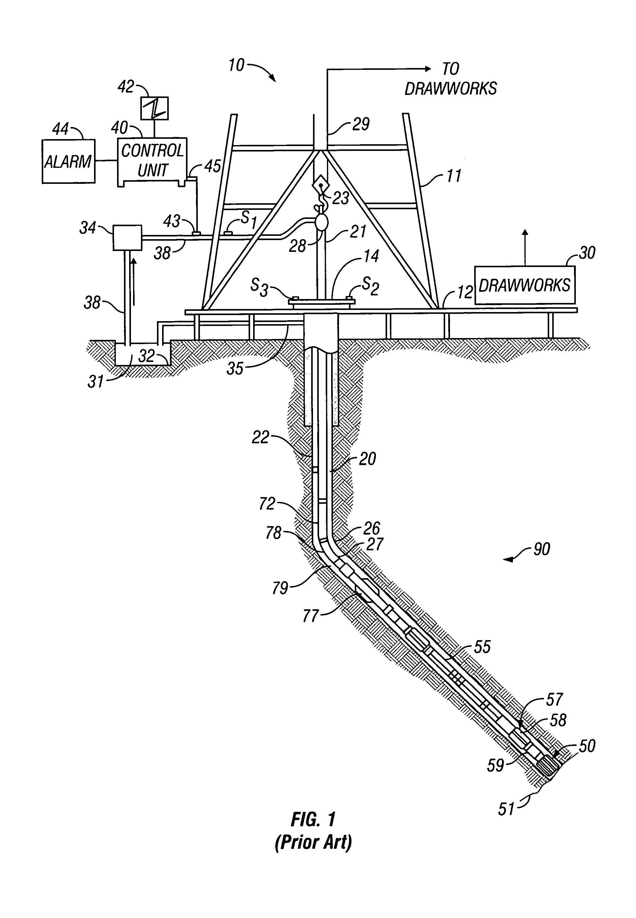
[0039]FIG. 1 shows a schematic diagram of a drilling system 10 with a drillstring 20 carrying a drilling assembly 90 (also referred to as the bottom hole assembly, or “BHA”) conveyed in a “wellbore” or “borehole”26 for drilling the wellbore. The drilling system 10 includes a conventional derrick 11 erected on a floor 12 which supports a rotary table 14 that is rotated by a prime mover such as an electric motor (not shown) at a desired rotational speed. The drillstring 20 includes a tubing such as a drill pipe 22 or a coiled-tubing extending downward from the surface into the borehole 26. The drillstring 20 is pushed into the wellbore 26 when a drill pipe 22 is used as the tubing. For coiled-tubing applications, a tubing injector, such as an injector (not shown), however, is used to move the tubing from a source thereof, such as a reel (not shown), to the wellbore 26. The drill bit 50 attached to the end of the drillstring breaks up the geological formations when it is rotated to dri...


PUM


Abstract

An apparatus and method is discussed for characterizing a fluid sample downhole of aliphatic hydrocarbon compounds, aromatic hydrocarbon compound, or connate mud filtrates containing carbon-13 isotopes using an enhanced nuclear magnetic resonance (NMR) signal on a measurement-while-drilling device. To enhance the carbon-13 NMR signal these nuclei are being hyperpolarized. Either the Overhauser Effect (OE) or the Nuclear Overhauser Effect or optical pumping and the Spin Polarization Induced Nuclear Overhauser Effect (SPINOE) can serve as a mechanism for hyperpolarization of the carbon-13 nuclei.

Description

CROSS REFERENCE TO RELATED APPLICATIONS[0001]This patent application is a continuation-in-part of and claims priority from U.S. patent application Ser. No. 10 / 404,408, entitled “A Method and Apparatus for Combined NMR and Formation Testing For Assessing Relative Permeability with Formation Testing and Nuclear Magnetic Resonance Testing”, by Georgi, et al filed on Apr. 1, 2003, which is incorporated herein by reference in its entirety, and which is a continuation-in-part of and claims priority from U.S. patent application Ser. No. 09 / 910,209 entitled “Apparatus and Method for In Situ Analysis of Formation Fluids” by Krueger et al., filed on Jul. 20, 2001 now U.S. Pat. No. 6,609,568, which is incorporated herein by reference in its entirety. U.S. patent application Ser. No. 10 / 404,408 claims priority from U.S. patent application Ser. No. 60 / 369,268 entitled, “Combined NMR and Formation Testing” by Georgi et al. filed on Apr. 2, 2002, and claims priority from U.S. patent application Se...

Claims


Application Information

Patent Timeline
Patent Type & Authority Patents(United States)
IPC IPC(8): G01V3/00E21B49/00E21B49/08G01R33/28G01R33/44G01R33/62G01V3/32
CPCE21B49/00E21B49/08G01N24/081G01R33/5617G01R33/62G01V3/32G01R33/281G01R33/5601G01R33/5605
Inventor BLANZ, MARTINKRUSPE, THOMAS
Owner BAKER HUGHES HLDG LLC
Why Eureka
Try Eureka