Method of manufacturing a stent delivery system

a delivery system and manufacturing method technology, applied in the field of medical stents, can solve the problems of difficult manufacturing of the aforementioned crocheted cord delivery system, inability to manufacture stents, and inability to meet the needs of self-expandable stents with limited axial strength,

Inactive Publication Date: 2006-10-31
SCI MED LIFE SYST
View PDF28 Cites 33 Cited by
  • Summary
  • Abstract
  • Description
  • Claims
  • Application Information

AI Technical Summary

Benefits of technology

[0034]The subject method preferably further comprises, before said compressing step, the step of fixing a stent engaging sleeve to said inner catheter, said self-expandable stent surrounding said stent engaging sleeve, said stent engaging sleeve having an outer surface adapted to engage said self-expandable stent in such a way as to deter said self-expandable stent from sliding proximally relative thereto.

Problems solved by technology

Although the above-described coaxial tube delivery system is well-suited for many types of self-expandable stents, such a delivery system is not particularly well-suited for those self-expandable stents that have limited axial strength, such as the Strecker stent—a knitted nitinol wire stent disclosed in U.S. Pat. No 5,366,504 and commercially available from Boston Scientific Corporation, Natick, Mass.
This is because such stents are often unable to resist becoming axially compressed during assembly of the coaxial tube delivery system, when the distal end of the outer catheter must be drawn across the stent, and / or during deployment of the coaxial tube delivery system, when the distal end of the outer catheter must be withdrawn across the stent.
Unfortunately, the manufacture of the aforementioned crocheted cord delivery system is typically performed manually and can be quite taxing physically as a great deal of strength is required to tightly stretch the stent down on the catheter while crocheting the cord around the stent.
Another problem with the foregoing system is that, during deployment, the crocheted cord does not always unravel correctly and completely.

Method used


Image

  • Method of manufacturing a stent delivery system
  • Method of manufacturing a stent delivery system
  • Method of manufacturing a stent delivery system

Examples


first embodiment

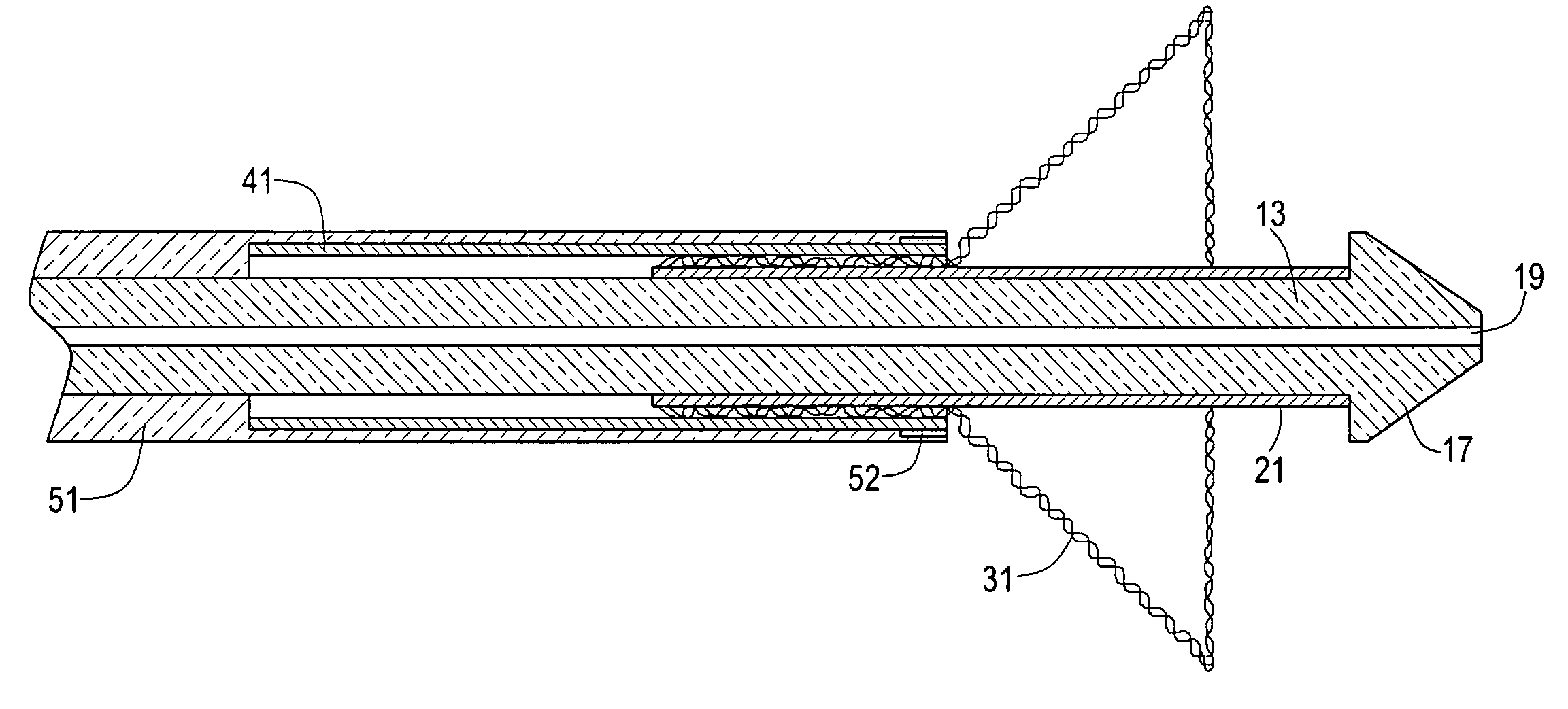
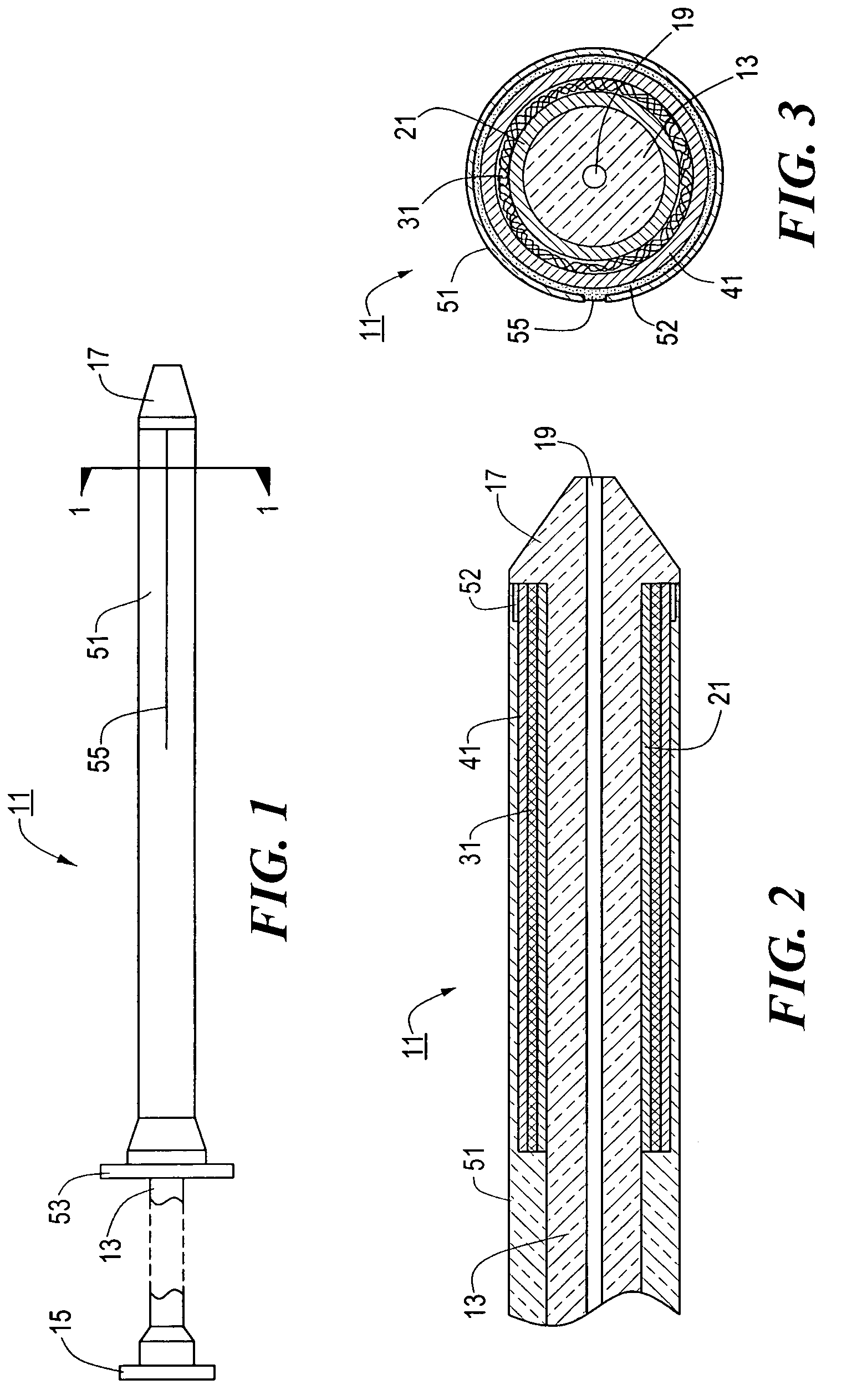
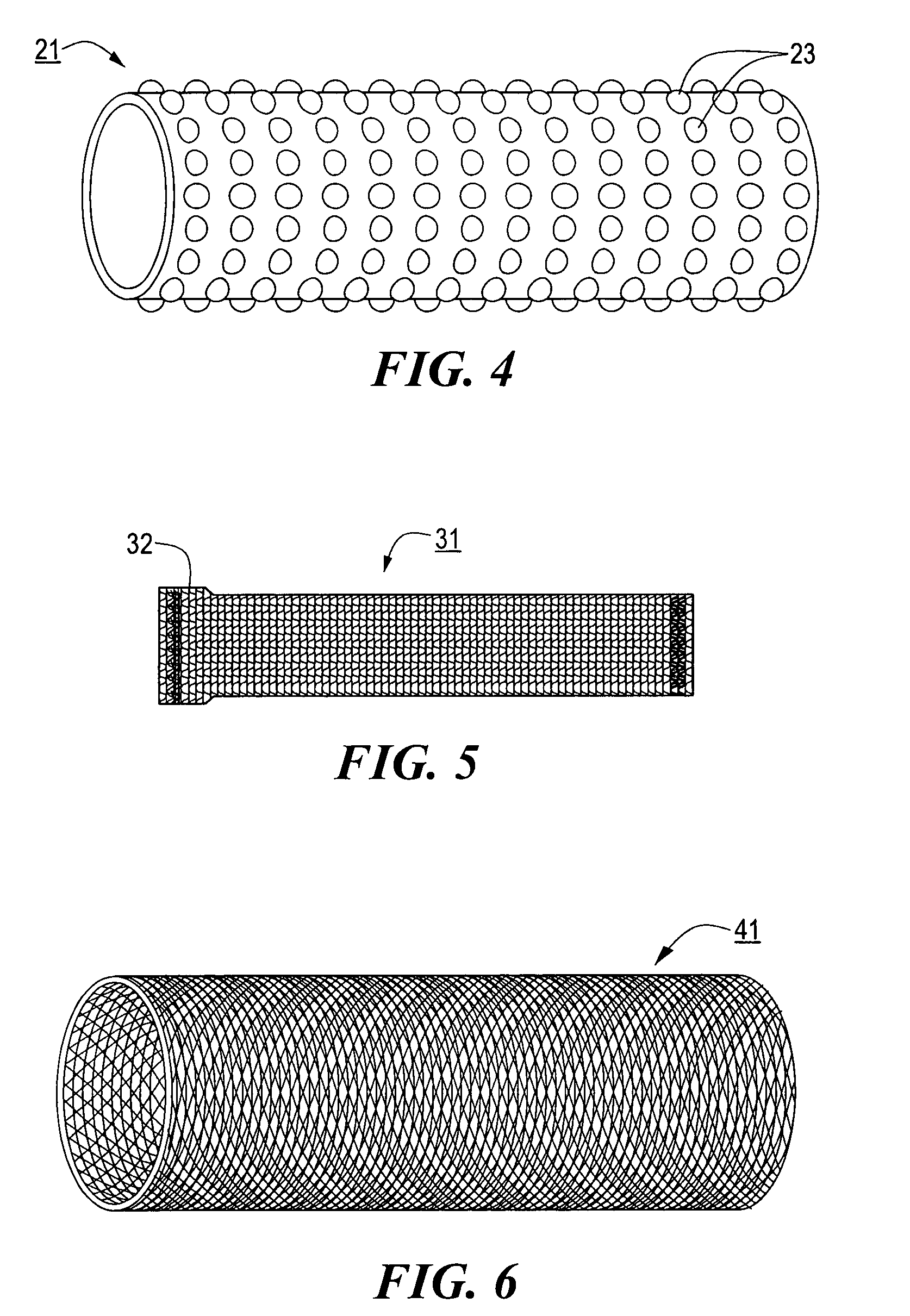
[0053]Referring now to FIGS. 1 through 3, there are shown various views of a stent delivery system constructed according to the teachings of the present invention, said stent delivery system being represented generally by reference numeral 11.

[0054]System 11 comprises a flexible, inner catheter 13. A handle 15 is disposed at the proximal end of catheter 13, and an enlarged tip 17 is disposed at the distal end of catheter 13. A lumen 19 extends longitudinally through catheter 13, lumen 19 being adapted to receive a guide wire for use in positioning system 11 at a desired position within a body lumen.

[0055]System 11 further comprises a stent engaging sleeve 21, sleeve 21 coaxially surrounding and secured (e.g., by a frictional fit) to that portion of catheter 13 proximally contiguous to tip 17. The primary purpose of sleeve 21 is to engage a stent mounted thereover in such a way as to prevent said stent, during deployment, from sliding proximally relative to catheter 13. To this end, ...

third embodiment

[0065]Referring now to FIGS. 10 and 11, there are shown longitudinal and transverse section views, respectively, of a stent delivery system constructed according to the teachings of the present invention, said stent delivery system being represented generally by reference numeral 101.

[0066]System 101 is similar in most respects to system 11, the principal difference between the two systems being that system 101 does not include sleeve 41 of system 11. Instead, system 101 relies on catheter 51 to function as the external restraint mechanism for keeping stent 31 in its compressed state until deployment. A lubricant (not shown) may be applied to the inside surface of catheter 51 to ensure that stent 31 does not axially compress, during deployment, as catheter 51 is moved proximally. As can readily be appreciated, catheter 51 of system 101 could be replaced with catheter 51′ and jacket 61.

[0067]System 101 is used in the same manner as system 11.

fourth embodiment

[0068]Referring now to FIGS. 12 and 13, there are shown longitudinal and transverse section views, respectively, of a stent delivery system constructed according to the teachings of the present invention, said stent delivery system being represented generally by reference numeral 201.

[0069]System 201 is similar in most respects to system 11, the principal difference between the two systems being that system 201 comprises, instead of sleeve 41, a stent restraining element in the form of a single helical coil 203 wrapped around stent 31. Coil 203 may be made of wire, thread, ribbon or like materials and may be wrapped around stent 31 either manually or with the use of an automated winding machine. The distal end of coil 203 is coupled to the distal end of catheter 51. One advantage to using coil 203, instead of sleeve 41, is that it is less complicated and less costly, particularly in terms of automated equipment, to apply a single, coiled containment element than it is to apply multi...


PUM

PropertyMeasurementUnit
diameteraaaaaaaaaa
diameteraaaaaaaaaa
lengthaaaaaaaaaa

Abstract

In one embodiment, the stent delivery system comprises an inner catheter. A handle is disposed at the proximal end of the inner catheter, and an enlarged tip is disposed at the distal end thereof. A stent engaging sleeve coaxially surrounds and is secured to a portion of the inner catheter proximally contiguous to the tip. A stent is mounted over the stent engaging sleeve in a longitudinally stretched state and is maintained, until deployment, in the stretched state by a stent restraining sleeve. The stent restraining sleeve, which coaxially surrounds the stent and is appropriately sized to maintain the stent in its stretched state, is a braided tube formed directly over the stent. The system also includes an outer catheter that surrounds much of the distal end of the inner catheter up to its tip, the outer catheter being adapted for axial movement relative to the inner catheter.

Description

CROSS-REFERENCE TO RELATED APPLICATIONS[0001]The present application is a continuation of U.S. patent application Ser. No. 09 / 767,212, filed Jan. 22, 2001 now U.S. Pat. No. 6,699,274 B2, the disclosure of which is incorporated herein by reference.BACKGROUND OF THE INVENTION[0002]The present invention relates generally to medical stents (hereinafter “stents”) and relates more particularly to stent delivery systems.[0003]A stent is a tubular endoprosthesis placed within a body lumen to maintain its patency. For example, a stent may be used to maintain the patency of an esophagus or other passageway occluded by a tumor or of a blood vessel constricted by plaque. Most stents fall into one of the following two classes: (i) balloon-expandable stents; and (ii) self-expandable stents. Generally speaking, a stent delivery system includes the stent and some means for positioning and fixing the stent in place within a body lumen.[0004]A balloon-expandable stent is typically a ductile metal tub...

Claims


Application Information

Patent Timeline
Patent Type & Authority Patents(United States)
IPC IPC(8): A61M25/00A61F2/06B21D39/00A61F2/90
CPCA61F2/90A61F2/95A61F2/966A61F2/97A61F2002/9665Y10T29/49913A61F2220/0058Y10T29/4984Y10T29/49929Y10T29/49966Y10T29/49908A61F2220/005A61F2/92
Inventor STINSON, JONATHAN S.
Owner SCI MED LIFE SYST
Why Eureka
Try Eureka