Process for fabricating monolithic membrane substrate structures with well-controlled air gaps

a monolithic membrane substrate and air gap technology, applied in the direction of microstructural devices, layered products, transportation and packaging, etc., can solve the problem that the height of the sacrificial layer does not determine the size of the air gap, and achieve the effect of low loss

Inactive Publication Date: 2006-10-31
HRL LAB
View PDF7 Cites 11 Cited by
  • Summary
  • Abstract
  • Description
  • Claims
  • Application Information

AI Technical Summary

Benefits of technology

[0009]The present invention discloses a process for fabricating a monolithic structure having an air gap and consisting of a preferably polyimide membrane on a patterned silicon substrate. The process and resulting device do not require bonding of two separate sections to achieve the air gaps. The structure is easy to fabricate, reliable, and can be miniaturized using standard cleanroom processing techniques. Therefore, the size of the gap can be controlled with extreme precision. Furthermore, any desired layer can be patterned on the membrane or substrate surfaces forming the micro-chamber. The metal layers can easily be used as electrodes for electrostatic actuation of the membrane, providing tuning capability for any application. The process and resulting device relies on the use of an intermediate sacrificial layer to release the membrane. However, unlike conventional techniques, the height of the sacrificial layer does not determine the size of the air gap that is eventually obtained. This represents a significant advantage in fabricating tunable electronic components that require relatively large air gaps that would be impossible or extremely cost prohibitive to realize using conventional methods. The process also ensures that the polyimide membrane retains the desirable tensile stress.
[0017]The main purpose of the air gap structure is to realize tunable RF capacitors with an air dielectric (for low loss), for use in tunable filters and phase shifters. In particular, the filters and phase shifters can be tuned by controlling the movement of the membrane.

Problems solved by technology

However, unlike conventional techniques, the height of the sacrificial layer does not determine the size of the air gap that is eventually obtained.

Method used


Image

  • Process for fabricating monolithic membrane substrate structures with well-controlled air gaps
  • Process for fabricating monolithic membrane substrate structures with well-controlled air gaps
  • Process for fabricating monolithic membrane substrate structures with well-controlled air gaps

Examples


Embodiment Construction

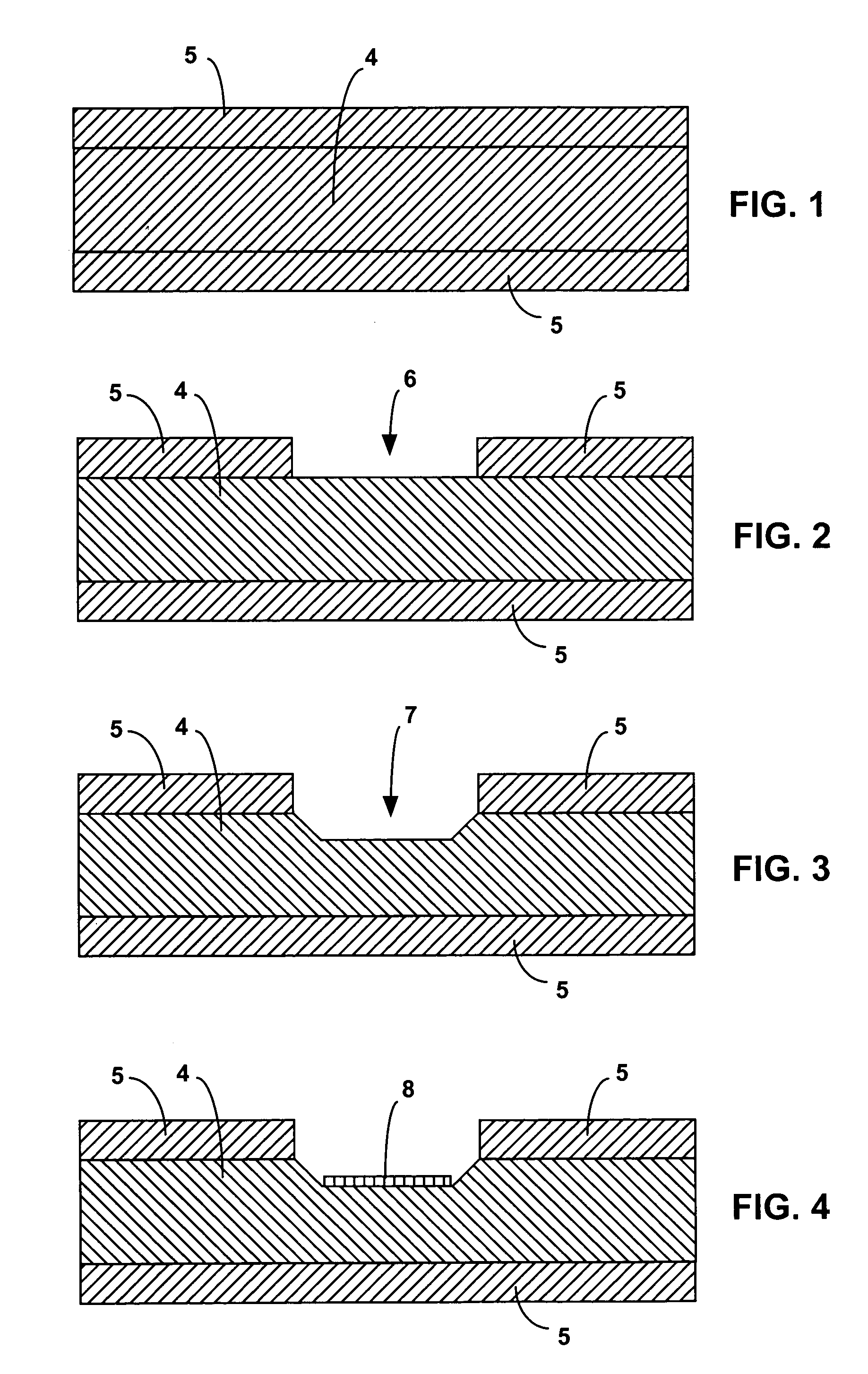
[0024]In one embodiment of the current invention a silicon substrate or wafer 4 has protective layers 5 of Si3N4 deposited on both sides of the silicon wafer by, for example, plasma enhanced chemical vapor deposition (PECVD), as shown in FIG. 1. Preferably, the layers 5 are about 0.5 μm thick.

[0025]A window 6, as shown in FIG. 2, is then patterned in one of the layers 5 so that the silicon wafer 4 lying underneath the layer 5 can be etched.

[0026]Next, a trench 7, shown in FIG. 3, is etched in the silicon wafer 4. Preferably, the etchant used in this step is a KOH solution and the trench 7 has a depth of between about 5 and about 50 μm.

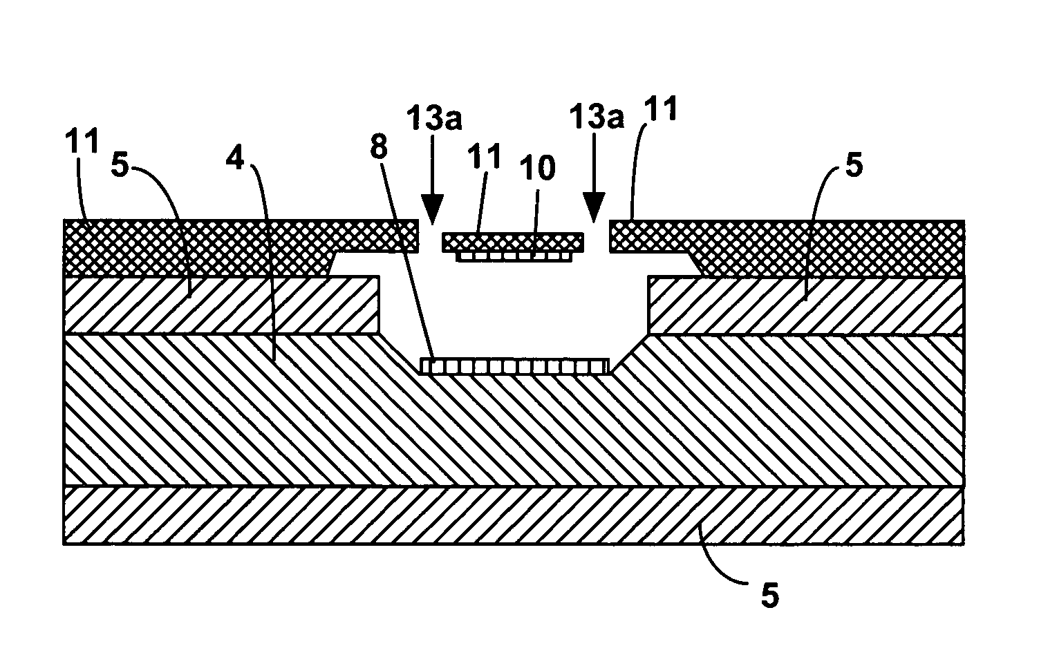
[0027]A metal pad 8, an example of which is shown in FIG. 4, is deposited and patterned in the trench 7. Preferably the metal pad 8 consists of a Ti—Au film having a thickness of about 1 μm. The metal pad 8 can be, for example, an electrode for electrostatic actuation.

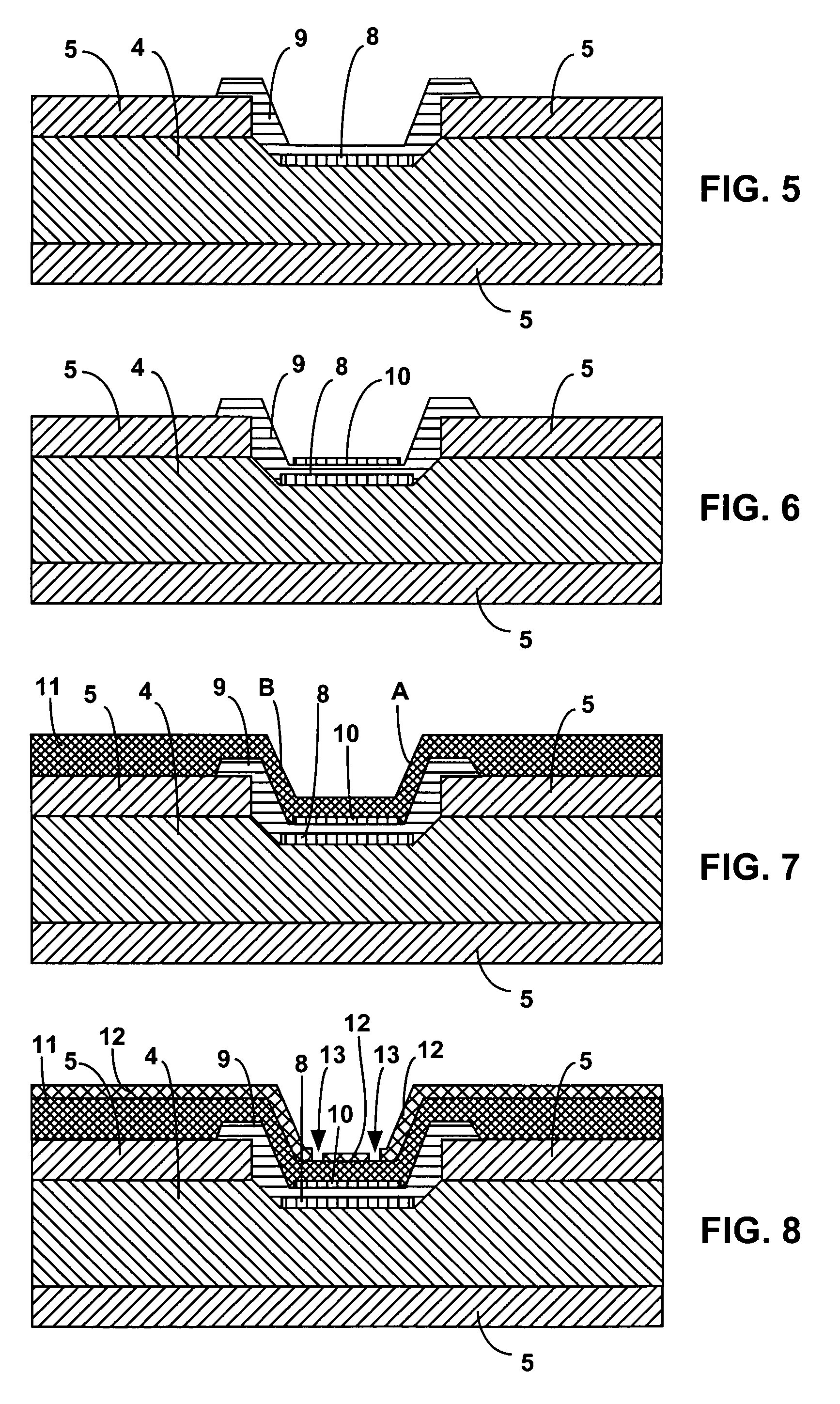
[0028]The following figures show embodiments where the upper protective layer 5 is pr...


PUM

PropertyMeasurementUnit
thickaaaaaaaaaa
depthaaaaaaaaaa
depthaaaaaaaaaa

Abstract

A process for fabricating monolithic membrane structures having air gaps is disclosed, comprising the steps of: providing a wafer; depositing and patterning a protective layer on the wafer; providing a trench in the wafer; depositing and patterning a metal in the trench; depositing and patterning a sacrificial layer on the metal; depositing and patterning a membrane pad on the sacrificial layer; providing a polymeric film on the protective layer and sacrificial layer, wherein part of the polymeric film has a tensile stress; and releasing part of the polymeric film from the protective layer and sacrificial layer, wherein the tensile stress of a portion of the polymeric film releases the portion of the polymeric film from the wafer and generates the air gap.

Description

CLAIM OF BENEFIT OF PROVISIONAL APPLICATION[0001]This application claims the benefit of U.S. provisional application Ser. No. 60 / 460,524 filed on Apr. 4, 2003, which is incorporated herein by reference in its entirety.BACKGROUND OF THE INVENTION[0002]1. Field of the Invention[0003]The present invention relates to a process for fabricating a monolithic structure comprising a polymeric membrane on a patterned substrate and to a monolithic membrane-substrate structure. The monolithic membrane-substrate structure has a well-controlled air gap in between.[0004]2. Description of the Related Art[0005]Prior fabrication processes for making structures with well-controlled air gaps have used sacrificial layers to form the gap. However, the use of sacrificial layers to form release membranes or cantilever type structures suffers from certain limitations. The size of the air gap obtained from these processes is determined entirely by the height of the sacrificial layer. Since deposition of any ...

Claims


Application Information

Patent Timeline
Patent Type & Authority Patents(United States)
IPC IPC(8): H01L21/00B32B3/00B81B3/00
CPCB81C1/00158Y10T428/24479Y10T428/2462B81C2201/014
Inventor MEHTA, SARABJIT
Owner HRL LAB
Why Eureka
Try Eureka