Electron beam physical vapor deposition process

a technology of physical vapor deposition and electron beam, which is applied in the direction of vacuum evaporation coating, superimposed coating process, electric/magnetic/electromagnetic heating, etc., can solve the problems of increasing the difficulty of controlling the electron beam, the high temperature durability of the components of the engine must correspondingly increase, and the high-temperature capabilities of these alloys alone are often inadequate for components located in certain sections of the gas turbine engine. achieve the effect of enhancing the operation

Inactive Publication Date: 2006-10-31
GENERAL ELECTRIC CO
View PDF14 Cites 11 Cited by
  • Summary
  • Abstract
  • Description
  • Claims
  • Application Information

AI Technical Summary

Benefits of technology

[0010]According to the present invention, the operation of the EBPVD apparatus can be enhanced by the inclusion or adaptation of one or more features and / or process modifications. According to one aspect of the invention relating to process temperature control, the coating chamber contains radiation reflectors that can be moved within the coating chamber to increase and decrease the amount of reflective heating that the article receives from the molten coating material during a coating campaign. Process pressure control is also an aspect of the invention, by which processing pressures of greater than 0.010 mbar can be practiced in accordance with copending U.S. patent application Ser. No. 09 / 108,201 to Rigney et al. (assigned to the same assignee as the present invention) with minimal or no adverse effects on the operation and reliability of the electron beam gun, and with minimal fluctuations in process pressures. Mechanical and process improvements directed to this aspect of the invention include modifications to the electron beam gun, the coating chamber, and the manner by which gases are introduced and removed from the apparatus. Also improved by this invention is the electron beam pattern on the coating material.
[0011]According to another preferred aspect of the invention, a crucible is employed to support the coating material within the coating chamber. The crucible preferably comprising at least two members, a first of which surrounds and retains a molten pool of the coating material, while the second member is secured to the first member and surrounds an unmolten portion of the coating material. The first and second members define an annular-shaped cooling passage therebetween that is closely adjacent the molten pool, so that efficient cooling of the crucible can be achieved, reducing the rate at which the process temperature increases within the coating chamber.
[0012]Another preferred aspect of the invention entails a rotatable magazine that supports multiple ingots of the coating material beneath the coating chamber. The magazine is indexed to individually align multiple stacks of one or more ingots with an aperture to the coating chamber for sequentially feeding the ingots into the coating chamber without interrupting deposition of the coating material.

Problems solved by technology

However, as operating temperatures increase, the high temperature durability of the components of the engine must correspondingly increase.
While significant advances have been achieved with iron, nickel and cobalt-base superalloys, the high-temperature capabilities of these alloys alone are often inadequate for components located in certain sections of a gas turbine engine, such as the turbine, combustor and augmentor.
Higher pressures are avoided because control of the electron beam is more difficult at pressures above about 0.005 mbar, with erratic operation being reported at coating chamber pressures above 0.010 mbar.
It has also been believed that the life of the electron beam gun filament would be reduced or the gun contaminated if operated at pressures above 0.005 mbar.
However, limitations of the prior art are often the result of the relatively narrow range of acceptable coating temperatures, the complexity of moving extremely hot components into and out of the coating chamber, and the difficulties confronted when maintaining an advanced EBPVD apparatus.

Method used


Image

  • Electron beam physical vapor deposition process
  • Electron beam physical vapor deposition process
  • Electron beam physical vapor deposition process

Examples


Embodiment Construction

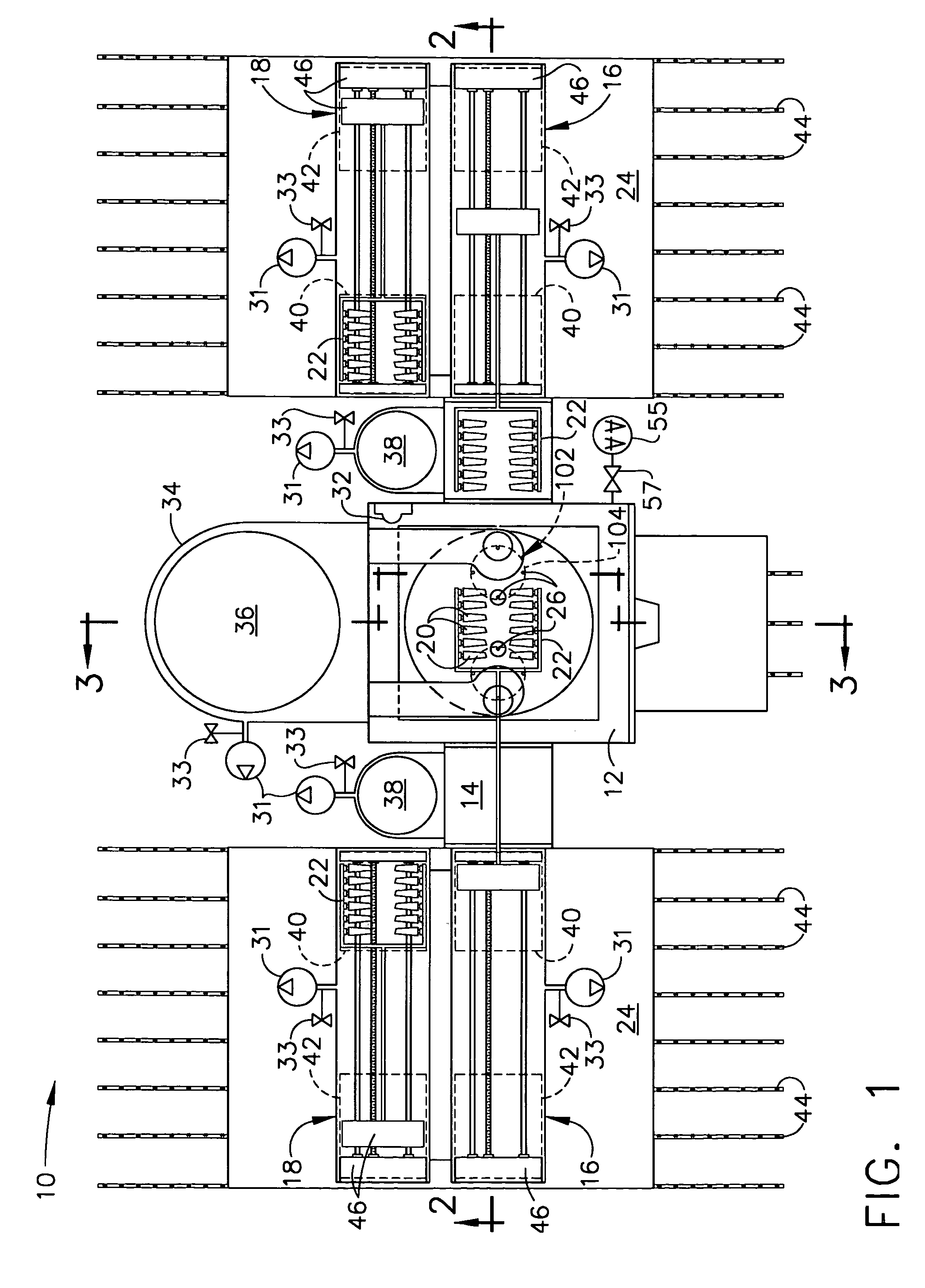
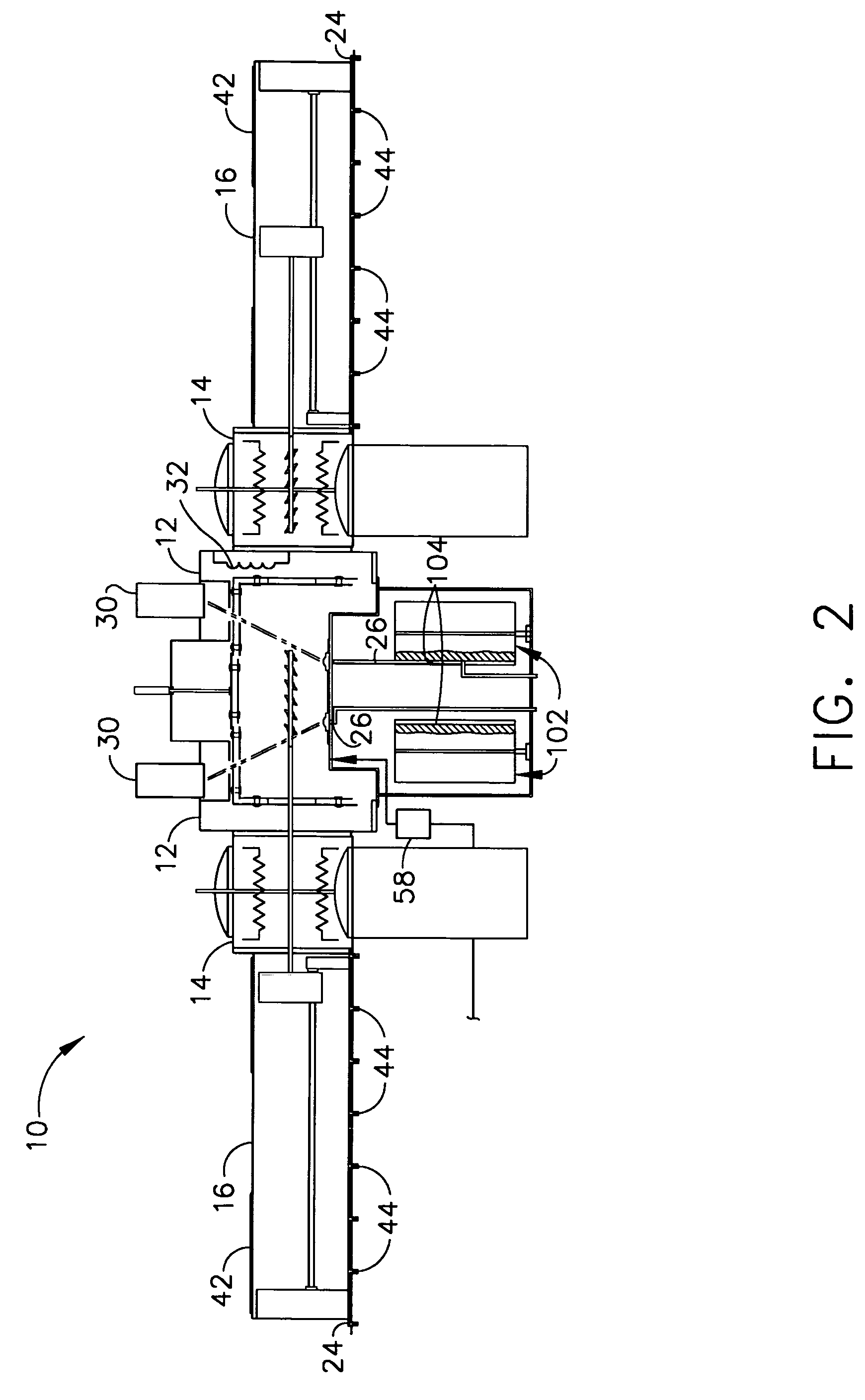
[0024]An EBPVD apparatus 10 in accordance with this invention is generally depicted in FIGS. 1 and 2, with various components and features being depicted in FIGS. 3 through 14. The apparatus 10 is particularly well suited for depositing a ceramic thermal barrier coating on a metal component intended for operation within a thermally hostile environment. Notable examples of such components include the high and low pressure turbine nozzles and blades, shrouds, combustor parts and augmentor hardware of gas turbine engines. While the advantages of this invention will be described with reference to depositing a ceramic coating on such components, the teachings of this invention can be generally applied to a variety of coating materials and components.

[0025]For purposes of illustrating the invention, the EBPVD apparatus 10 is shown in FIGS. 1 and 2 as including a coating chamber 12, a pair of preheat chambers 14, and two pairs of loading chambers 16 and 18, so that the apparatus 10 has a s...


PUM

PropertyMeasurementUnit
pressureaaaaaaaaaa
pressureaaaaaaaaaa
pressuresaaaaaaaaaa

Abstract

An electron beam physical vapor deposition (EBPVD) process performed with a coating apparatus to produce a coating material (e.g., a ceramic thermal barrier coating) on an article. The EBPVD apparatus generally includes a coating chamber operated at an elevated temperature and a subatmospheric pressure. The coating chamber contains a crucible and a coating material surrounded by and contained within the crucible, and the coating material has a surface exposed by the crucible. The process entails projecting an electron beam onto the surface of the coating material, wherein the electron beam defines a beam pattern having a higher intensity at an interface of the surface of the coating material with the crucible than at a central region of the surface of the coating material.

Description

[0001]This application is a divisional patent application of U.S. patent application Ser. No. 09 / 624,810, filed Jul. 24, 2000, now U.S. Pat. No. 6,983,718.[0002]This application claims benefit of Provisional Patent Application No. 60 / 147,232, filed Aug. 4, 1999, which is hereby incorporated by reference.FIELD OF THE INVENTION[0003]This invention generally relates to an electron beam physical vapor deposition coating apparatus. More particularly, this invention is directed to such a coating apparatus adapted to deposit ceramic coatings on components, such as thermal barrier coatings on superalloy components of gas turbine engines.BACKGROUND OF THE INVENTION[0004]Higher operating temperatures for gas turbine engines are continuously sought in order to increase their efficiency. However, as operating temperatures increase, the high temperature durability of the components of the engine must correspondingly increase. While significant advances have been achieved with iron, nickel and co...

Claims


Application Information

Patent Timeline
Patent Type & Authority Patents(United States)
IPC IPC(8): C23C14/30C23C14/08C23C14/54C23C28/00H01J37/305
CPCC23C14/083C23C14/30C23C14/548H01J37/3053H01J2237/3132
Inventor BRUCE, ROBERT WILLIAMEVANS, SR., JOHN DOUGLAS
Owner GENERAL ELECTRIC CO
Why Eureka
Try Eureka