Hybrid active combiner and circulator

a technology of active combiner and circulator, which is applied in the direction of amplifiers with semiconductor devices/discharge tubes, amplifiers with coupling networks, and low noise amplifiers. it can solve the problems of reducing the range of reflection coefficient that can be applied to the source port of the dut, and the active combiner of fet cannot meet the requirements of some applications

a technology of active combiner and circulator, which is applied in the direction of amplifiers with semiconductor devices/discharge tubes, amplifiers with coupling networks, and low noise amplifiers. it can solve the problems of reducing the range of reflection coefficient that can be applied to the source port of the dut, and the active combiner of fet cannot meet the requirements of some applications

US7129783B2Active Publication Date: 2006-10-31THE AEROSPACE CORPORATION

Image

  • Hybrid active combiner and circulator
  • Hybrid active combiner and circulator
  • Hybrid active combiner and circulator

Examples


Embodiment Construction

[0023]An embodiment of the invention is described with reference to the figures using reference designations as shown in the figures.

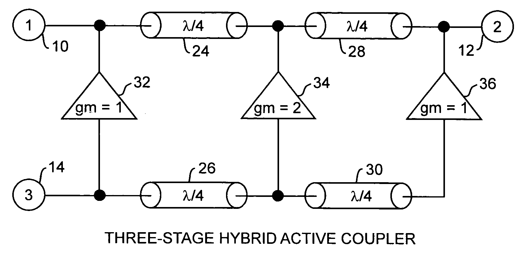
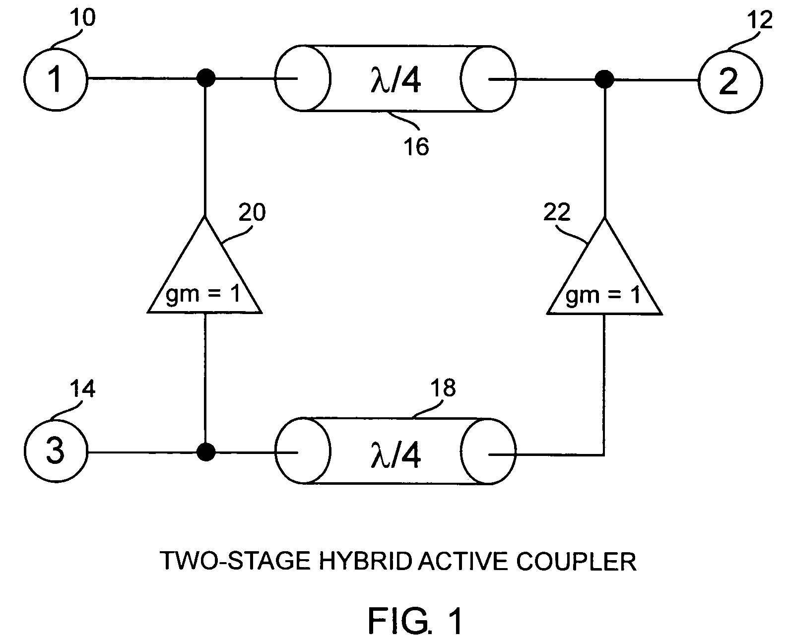
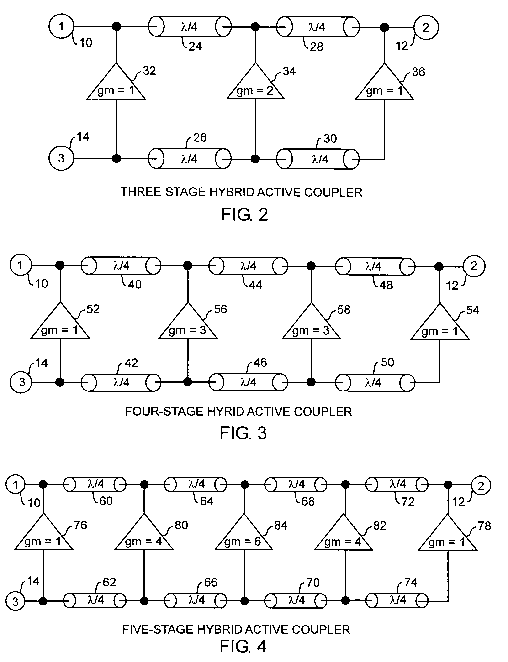
[0024]Referring to FIG. 1, a hybrid active coupler that functions as a combiner and a circulator, is a three-port network, having a first port 10, a second port 12 and a third port 14. This configuration is a the simplest form of the coupler as a two-stage network having two passive delays 16 and 18 and two transconductance amplifiers 20 and 22 each having a normalized transconductance of unity. Each stage is characterized by an amplifier. The amplifiers 20 and 22 are aligned in parallel, with the delay 16 connected across the outputs and delay 18 connected across the inputs of the amplifiers 20 and 22. An input signal into the third port 14 is connected to first and second ports 10, and 12, respectively, between which is disposed the delay 16. A passive signal path between ports 10 and 12 is designed to have minimal insertion loss. The port 14 is the ...


PUM


Abstract

The hybrid active combiner and circulators serves as a coupler and is a three port network that integrates a directional coupler topology with active devices placed in the coupling paths in order to synthesize a low-loss active combiner circuit or a circulator device with minimal insertion losses. The coupler can have multiple stage amplifiers with transconductance values set according the Pascal's triangle for improved performance, and can function as a low cost and low weight transceiver well suited for various communications systems.

Description

STATEMENT OF GOVERNMENT INTEREST[0001]The invention was made with Government support under contract No. F04701-00-C-0009 by the Department of the Air Force. The Government has certain rights in the invention.FIELD OF THE INVENTION[0002]The invention relates to the field of electrical couplers including combiners and circulators. More particularly, the present invention relates to active couplers for transceiving electrical signals.BACKGROUND OF THE INVENTION[0003]Signal combination can be accomplished by means of passive or active combiners. Passive combiners contain no active or nonlinear elements, such as transistors, while active combiners do contain active devices, such as amplifiers, that provide gain. Scattering or S-parameters often describe combiner performance. A four-port combiner has been used to combine signals. Input signals are input into two ports 1 and 4 and are output from the other two ports 2 and 3 depending on the relative phase of the input signals. The paths be...

Claims


Application Information

Patent Timeline
31 Oct 2006
Publication
US7129783B2
IPC
H03F3/60
CPC
H03F1/523; H03F3/191; H03F3/604; H03F2200/192; H03F2200/198; H03F2200/204; H03F2200/294; H03F2200/372
Inventors
YOUNG, ALBERT M.; OSOFSKY, SAMUEL S.