Eye position detection method and device

a detection method and eye position technology, applied in the field of image processing technology, can solve the problems of inability to detect, inability to detect, and inability to achieve detection, and achieve the effect of short time and high precision

Active Publication Date: 2006-10-31
PANASONIC CORP
View PDF15 Cites 123 Cited by
  • Summary
  • Abstract
  • Description
  • Claims
  • Application Information

AI Technical Summary

Benefits of technology

[0010]An object of the present invention is providing a method for detecting the position of an eye from a face image, in which the eye position can be detected with high precision in a short time from a

Problems solved by technology

Therefore, detection of an eye will not be successful when the technique of using gray-scale values as disclosed in (1) and the technique of using edge information obtained from gray-scale values as disclosed in (2) are directly applied to an eye image taken under near infrared light.
There is therefore a great possibility of detecting a position

Method used


Image

  • Eye position detection method and device
  • Eye position detection method and device
  • Eye position detection method and device

Examples


Embodiment Construction

[0054]Hereinafter, a preferred embodiment of the present invention will be described with reference to the accompanying drawings.

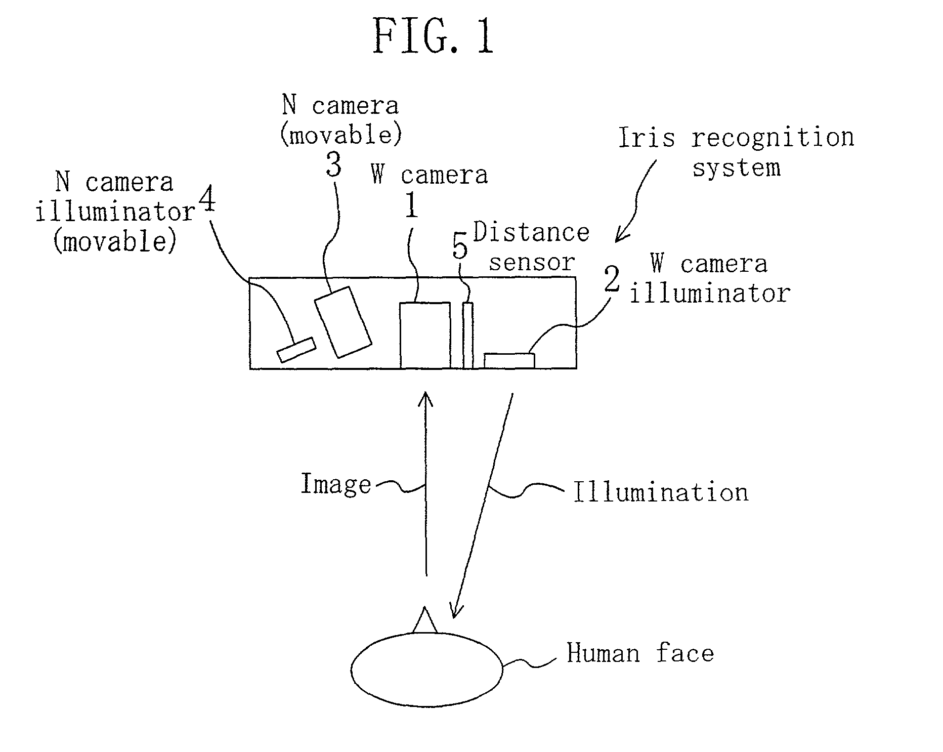
[0055]FIG. 1 is a view of a schematic configuration of an iris recognition system using the eye position detection according to the present invention. The iris recognition system of FIG. 1 has a 2-camera structure composed of a wide field of view (W) camera 1 and a narrow field of view (N) camera 3. The W camera 1 takes an image including at least an eye. A distance sensor 5 measures the distance from the eye. The N camera 3, which receives the position of the eye determined from the image taken by the W camera 1 and the distance from 10 the eye measured by the distance sensor 5, takes an enlarged image of the iris of the eye.

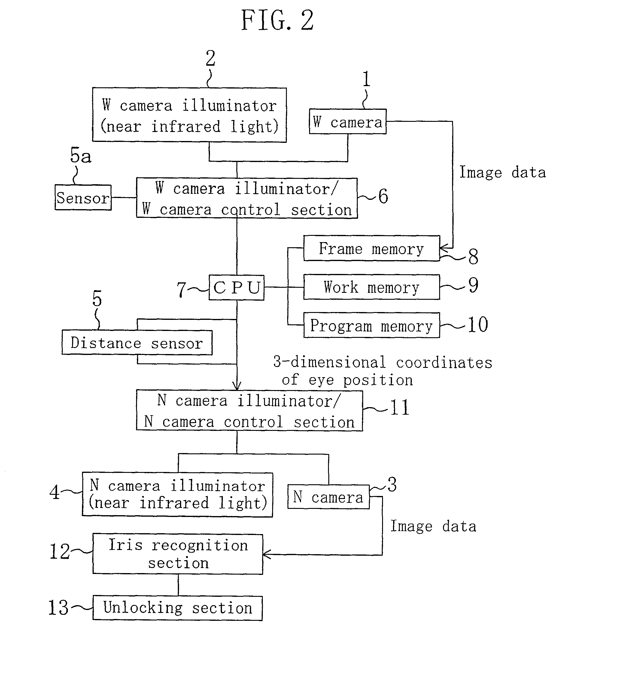
[0056]FIG. 2 is a block diagram of an entrance / exit control system as an example of a system using the iris recognition system shown in FIG. 1. Referring to FIG. 2, the W camera 1 and a W camera illuminator 2 are controlled by a W cam...


PUM


Abstract

The position of an eye is detectable with high precision from a face image of a person taken under near infrared illumination or the like. After pre-processing, the face image is subjected to brightness correction to increase the contrast between the sclera portion and iris portion of the eye. Brightness gradient vectors are calculated for the brightness-corrected image, and matching is performed between a brightness gradient image generated using the calculated brightness gradient vectors and an eye template. Further, matching with a pupil template is performed to correct the eye center position. Final positions of both eyes are then determined.

Description

BACKGROUND OF THE INVENTION[0001]The present invention relates to an image processing technology of detecting the position of an eye from a human face image for iris authentication and the like used for entrance / exit control and the like.[0002]In recent years, the technology of personal authentication using iris recognition has been gradually brought into commercial use in association with entrance / exit control, automatic teller machine (ATM), and the like. As an example of such commercial use, conceived is a system of detecting the position of an eye from a human face image taken and performing iris recognition using an enlarged image of the detected eye position.[0003]Techniques for detecting an eye from an image are disclosed in: (1) “Facial Feature Point Extraction Method Based on Combination of Shape Extraction and Pattern Matching”, The Institute of Electronics, Information and Communication Engineers, Transactions D-II, Vol. J80-D-II, No. 8, pp. 2170–2177, (2) Japanese Patent...

Claims


Application Information

Patent Timeline
IPC IPC(8): G06K9/00A61B5/117G06T1/00G06T7/00G06T7/60
CPCG06K9/00604G06K9/00617G06V40/19G06V40/197
Inventor KONDO, KENJIUOMORI, KENYA
Owner PANASONIC CORP
Why Eureka
Try Eureka