Optical transmission systems including optical amplifiers, apparatuses and methods

a technology of optical amplifiers and optical transmission systems, applied in the field of optical transmission systems, can solve the problems of limiting the performance of the system, and the optical fiber is not a perfect transmitter of electromagnetic radiation in the optical spectrum, so as to improve the performance and reliability, improve the performance of the composite filter, and reduce the noise of the pump source

Inactive Publication Date: 2006-11-07
OPTIC153 LLC
View PDF56 Cites 7 Cited by
  • Summary
  • Abstract
  • Description
  • Claims
  • Application Information

AI Technical Summary

Benefits of technology

[0023]In various embodiments, fiber Bragg gratings and other devices are used to control the optical noise in the optical energy supply by optical sources, such as semiconductor laser diodes, to provide for lower noise pump sources. The lower noise pump sources can be used to supply optical energy for amplification to various optical amplifiers, such as Raman and erbium / rare earth doped fiber amplifiers and to control the noise figure of the amplifier.
[0024]In addition, the system can include composite gain flattening filters that are used to modify the gain profile produced over a plurality of optical amplifiers. The composite gain flattening filter provides flexibility in the operation of the individual amplifiers, which can be dynamically controlled to accommodate changes in the system and to the optimize the performance of the composite filter.
[0025]Accordingly, the present invention addresses the aforementioned concerns by providing optical systems apparatuses, and methods having increased performance and reliability. These advantages and others will become apparent from the following detailed description.

Problems solved by technology

However, optical transmission systems are not free from attenuation and various forms of degradation that limit the performance of the systems.
For example, optical fiber is not a perfect transmitter of electromagnetic radiation in the optical spectrum.
In addition, optical noise, from signal attenuation, chromatic dispersion, nonlinear interactions, and other sources, will accumulate and propagate in the fiber along with the signal further degrading the quality of the signal.
Furthermore, optical systems generally are not operated in the identical manner, which requires that interfaces be provided to interconnect different optical systems.
While the development of optical amplifiers has greatly reduced the equipment costs associated with amplifiers in optical systems, there remain substantial operational costs.
Real estate and building acquisition and maintenance costs associated with optical amplifiers can be a sizable portion of the optical system operational costs, which suggests maximizing the distance between optical amplifiers in an optical system.
However, maximizing the distance between amplifiers can reduce the maximum distance that optical signals can be transmitted before having to be regenerated to overcome accumulated optical noise.
Furthermore, increasing the bit rate and / or the number of channels often requires that the transmission distance to be decreased, which increases the system cost.
The ability to increase the capacity of the system is limited by the optical signal degradations that occur in the system.
Safety concerns may further limit the total power that can be launched into the fiber.
In optical transmission systems employing standard transmission fiber, chromatic dispersion can severely degrade the optical signal quality and thereby limit the maximum transmission distance.
However, a problem with LD fiber arises from the interrelation of chromatic dispersion and nonlinear interactions.
In LD fiber there is much less walk-off between adjacent closely spaced channels resulting in longer interaction time between channels, which increases the nonlinear interaction and resulting degradation of the signal channels.
However, increasing the channel spacing generally reduces the total number of channels in the system.
The limitations imposed by nonlinear interactions become increasing problematic for LD fibers at relatively low transmission capacities and short distances.
The current methods of reducing the nonlinear interactions in LD fiber greatly decreases the optical system capacity and performance compared to equivalent systems employing standard fiber.
The capacity limitation resulting from non-linear interactions is not limited to LD fiber, but also plagues standard fiber, transmission systems.
This limitation will require increased capital and operating expenditures to expand optical communication system capacity.

Method used


Image

  • Optical transmission systems including optical amplifiers, apparatuses and methods
  • Optical transmission systems including optical amplifiers, apparatuses and methods
  • Optical transmission systems including optical amplifiers, apparatuses and methods

Examples


Embodiment Construction

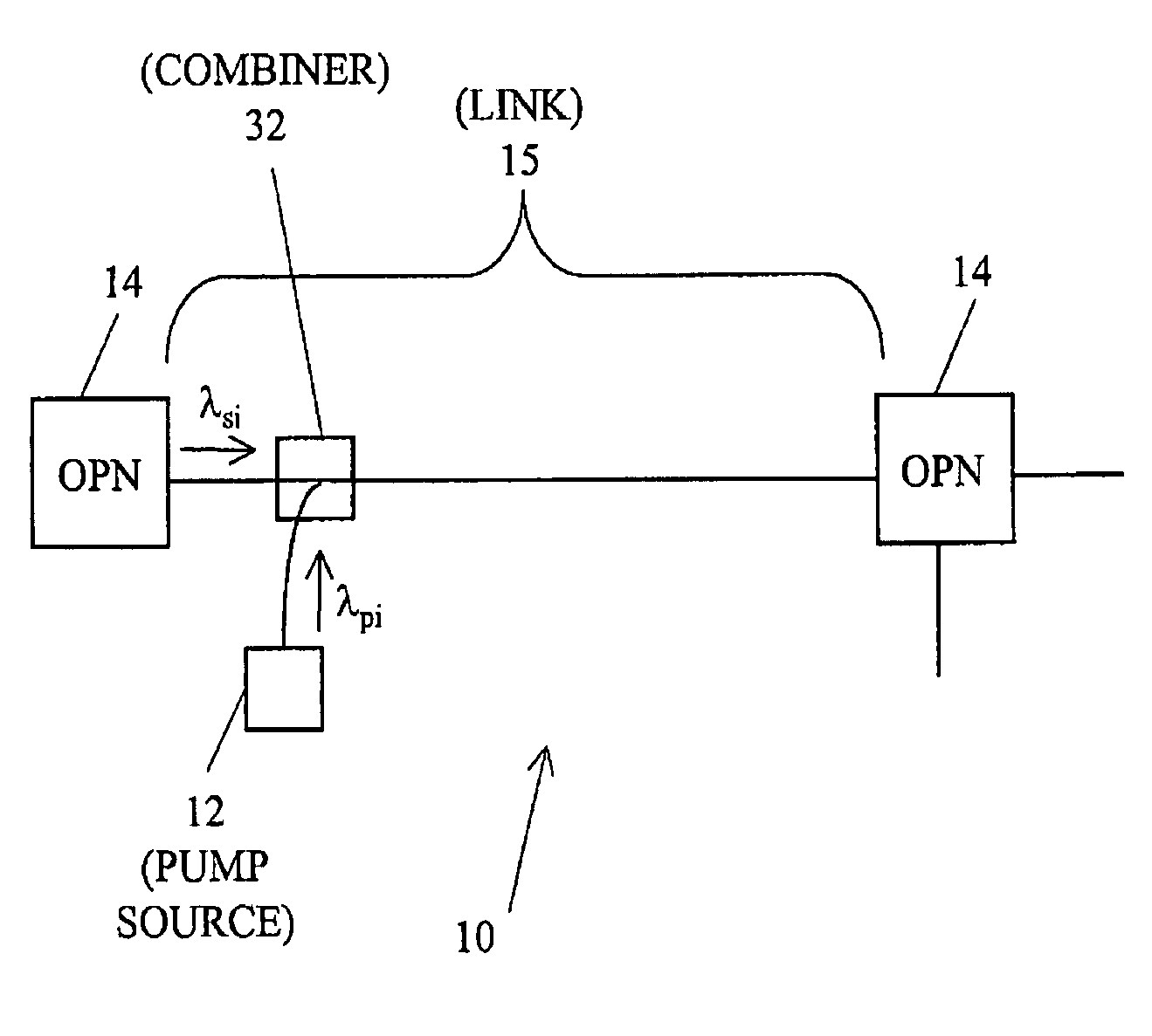
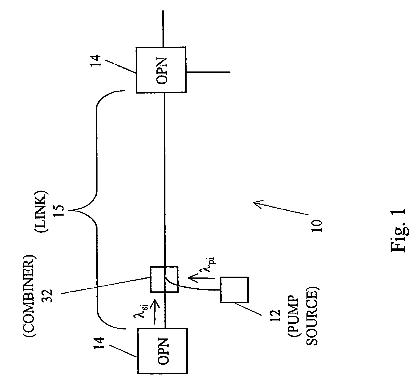
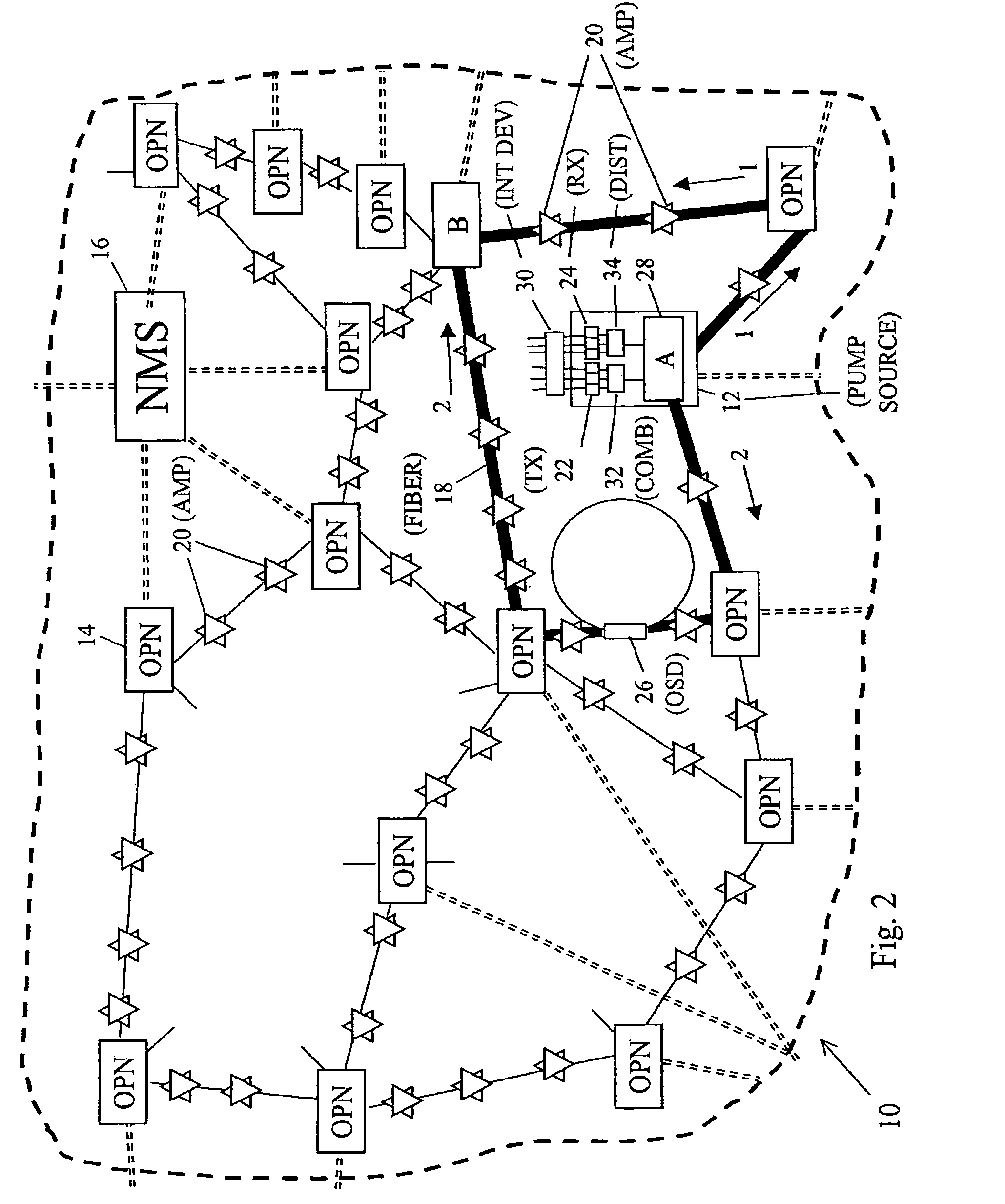
[0031]FIG. 1 shows an embodiment of an optical system 10, in which an optical energy pump source 12 is deployed between two optical nodes 14. The optical system 10 can be controlled by a network management system 16 and pump sources 12 configured to operate in one or more serially connected point to point links (FIG. 1) or in multi-dimensional networks (FIG. 2). The network management system 16 can communicate with the various nodes and elements in the optical systems 10 via wide area, data communication networks external to the system 10 and / or supervisory optical channels within the system 10.

[0032]The optical nodes 14 can be interconnected optically via guided and unguided transmission media, which is typically optical fiber waveguide 18. Optical amplifiers 20 typically will be provided along optical links 15 of sufficient length where amplification will be required to overcome optical signal attenuation or proximate other components to overcome component losses in the system 10....


PUM


Abstract

Optical systems of the present invention include amplifiers configured to achieve maximum signal channel in a span downstream of the transmitter and amplifier site and to decrease the interaction between the wavelengths at high signal channel powers. In addition, the system can include various types of optical fiber positioned in the network to provide for increased signal channel powers and higher gain efficiencies in the system.

Description

CROSS-REFERENCE TO RELATED APPLICATIONS[0001]This application is a continuation of U.S. patent application Ser. No. 10 / 046,962, filed Jan. 14, 2002, now U.S. Pat. No. 6,771,413, which is a continuation of U.S. patent application Ser. No. 09 / 540,708, filed Mar. 31, 2000, now U.S. Pat. No. 6,356,383, issued Mar. 12, 2002, which is a continuation-in-part (“CIP”) of commonly assigned U.S. Provisional Application No. 60 / 127,665 filed Apr. 2, 1999, all of which are incorporated herein by reference.STATEMENT REGARDING FEDERALLY SPONSORED RESEARCH OR DEVELOPMENT[0002]Not ApplicableBACKGROUND OF THE INVENTION[0003]The present invention is directed generally to optical transmission systems. More particularly, the invention relates to amplifying optical signals in optical transmission systems and controlling nonlinear interactions between signal channels, as well as the amplifier spacing in the optical systems.[0004]Optical communication systems transmit information by generating and sending o...

Claims


Application Information

Patent Timeline
Patent Type & Authority Patents(United States)
IPC IPC(8): H01S3/30H04J14/02H01S3/067H01S3/094H01S5/14H04B10/17
CPCH01S3/06758H01S3/302H04B10/2916H04B10/2941H01S3/0675H01S3/094011H01S5/146H04B2210/003
Inventor CORNWELL, JR., DONALD M.VESELKA, JR., JOHN J.GRUBB, STEPHEN G.STEPHENS, THOMAS D.JIN, RUXIANGPRICE, ALISTAIR J.ANTONE, MICHAEL C.
Owner OPTIC153 LLC
Why Eureka
Try Eureka