
Hydrated lime kiln dust recirculation method for gas scrubbing

a technology of hydrated lime and kiln dust, applied in the field of hydrocarbons, can solve problems such as pollution emission

Active Publication Date: 2006-11-28
GRAYMONT PA INC
View PDF10 Cites 31 Cited by
  • Summary
  • Abstract
  • Description
  • Claims
  • Application Information

AI Technical Summary

Benefits of technology

This self-sustaining method effectively removes pollutants like heavy metals, sulfur compounds, and greenhouse gases from flue gas, reducing environmental impact and operational costs by utilizing residual lime in kiln dust as a sorbent.

Problems solved by technology

The gas may contain some unwanted pollutants, which may become a problem in terms of pollution emission.

Method used


Image

  • Hydrated lime kiln dust recirculation method for gas scrubbing
  • Hydrated lime kiln dust recirculation method for gas scrubbing

Examples


Embodiment Construction

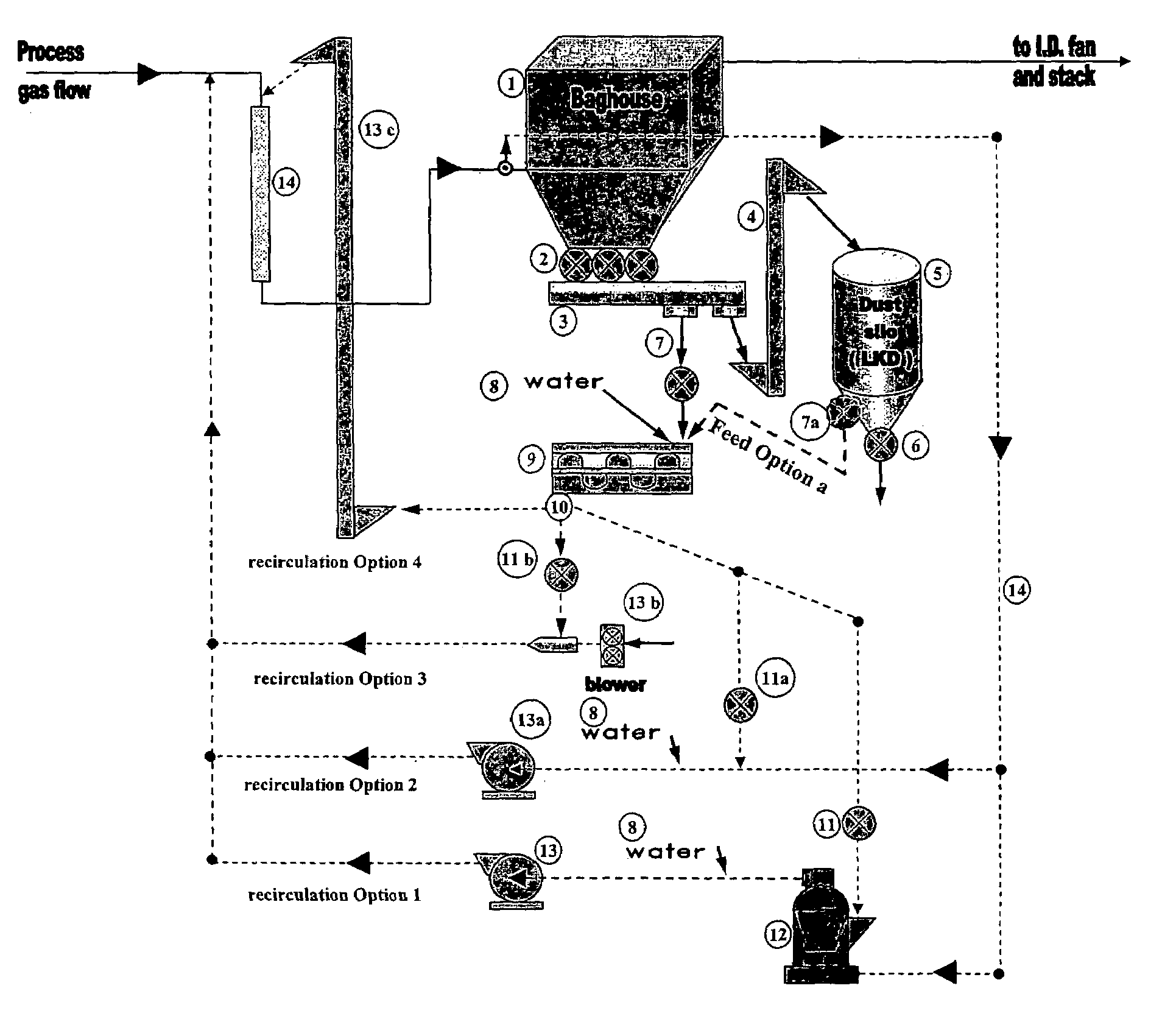
[0025]Referring now to FIG. 1, numeral 10 denotes the overall process. A baghouse 12 collects lime kiln dust from the lime / cement calcining procedure (not shown). From the baghouse 12 the dust is passed down to a collection point 14 which collection point 14 collects kiln dust material from all other sources (the other sources are not shown). The conveyance of the material from the baghouse to the collection point 14 is conducted in an airtight arrangement with the airlock being denoted by numeral 16. The collected dust is then passed to a conveyor 18. The conveyor may be any type of suitable conveyor such as a screw conveyor, bucket conveyor or any other suitable conveyor known to those skilled in the art. The material may be then transferred to a silo 20. The silo is equipped with a discharge device denoted by numeral 22. In the embodiment illustrated, the silo 22 includes a feeder 24 which is an optional feature to augment the feed that otherwise is delivered by feeder 26 directl...


PUM

PropertyMeasurementUnit
temperatureaaaaaaaaaa
scrubbing temperatureaaaaaaaaaa
temperatureaaaaaaaaaa

Abstract

A method of scrubbing a gas stream with re-circulated kiln dust when the kiln dust is hydrated to form a sorbent. The sorbent is re-circulated with un-reacted flue gas stream for scrubbing.

Description

FIELD OF THE INVENTION[0001]This application claims benefit of U.S. Provisional Application No. 60 / 491,962, filed Aug. 4, 2003.BACKGROUND OF THE INVENTION[0002]It is well established in the manufacturing of lime / cement products that limestone which is initially quarried exposed to additional unit operations for processing is eventually calcined with various kilns, examples of which are the vertical or rotary type kilns. In these kilns, the limestone is calcined at a high temperature, generally 1200° C. or greater at which point the material is converted to lime. In the calcination process carbon dioxide is removed from the calcium carbonate to leave calcium oxide. The lime may be hydrated by treatment with water to create calcium hydroxide which generally is in the form of a fine white powder which can be pulverized to any size distribution depending upon the final use of the product.[0003]In view of the fact that the kilns are used to generate high temperatures for the conversion p...

Claims


Application Information

Patent Timeline
Patent Type & Authority Patents(United States)
IPC IPC(8): B01D53/50B01D53/06B01D53/14B01D53/18
CPCB01D53/83B01D2251/404B01D2251/604B01D2257/2045B01D2257/2047B01D2257/302B01D2257/60B01D2257/602B01D2258/0233B01D2258/0283B01D2259/40007B01D2259/4009Y10S95/90
Inventor CHARETTE, ALAIN
Owner GRAYMONT PA INC
Learn More