Rotary electric machine and method for manufacturing the same

a technology of rotary electric machines and rotors, which is applied in the direction of stator/rotor bodies, magnetic circuit shapes/forms/construction, magnetic bodies, etc., can solve the problems of not being able to form all coil ends in a substantially identical manner, and achieve the effect of improving the cross-sectional ratio of conductors to slots, improving productivity, and convenient winding of stators

Inactive Publication Date: 2006-12-05
DENSO CORP
View PDF18 Cites 10 Cited by
  • Summary
  • Abstract
  • Description
  • Claims
  • Application Information

AI Technical Summary

Benefits of technology

[0011]Since the stator winding has a discontinuity, the stator winding may wound easily. In this arrangement, it is possible to improve a cross-sectional ratio of the conductors to the slot. Furthermore, it is possible to improve productivity by reducing complex manufacturing processes.

Problems solved by technology

However, this arrangement forms larger space in the slots to prevent the crossings of the coil ends.
However, it is necessary to handle a lot of segments and to accomplish a complex assembling process.
However, it is not easy to form all coil ends in a substantially identical manner.

Method used


Image

  • Rotary electric machine and method for manufacturing the same
  • Rotary electric machine and method for manufacturing the same
  • Rotary electric machine and method for manufacturing the same

Examples


first embodiment

[0030

[0031]An alternator for a vehicle according to a first embodiment of the present invention is described with reference to the drawings.

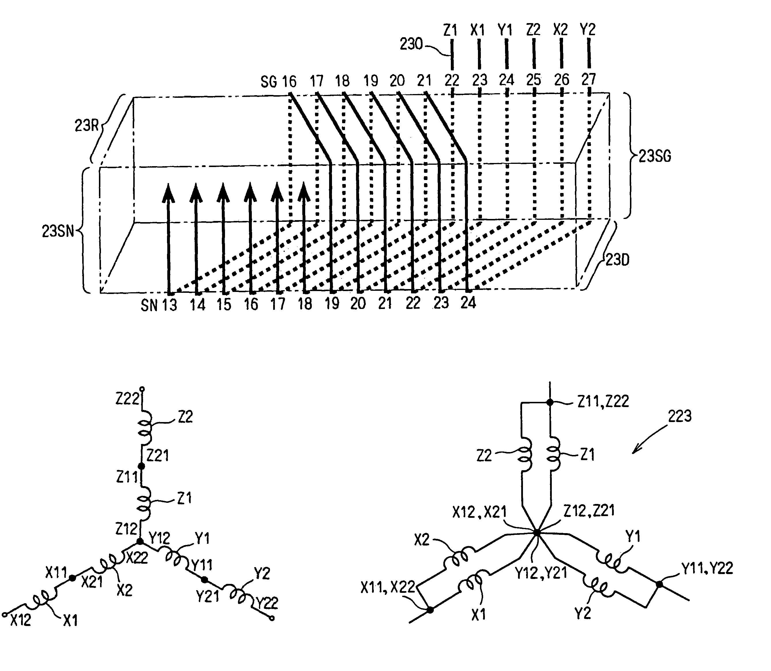
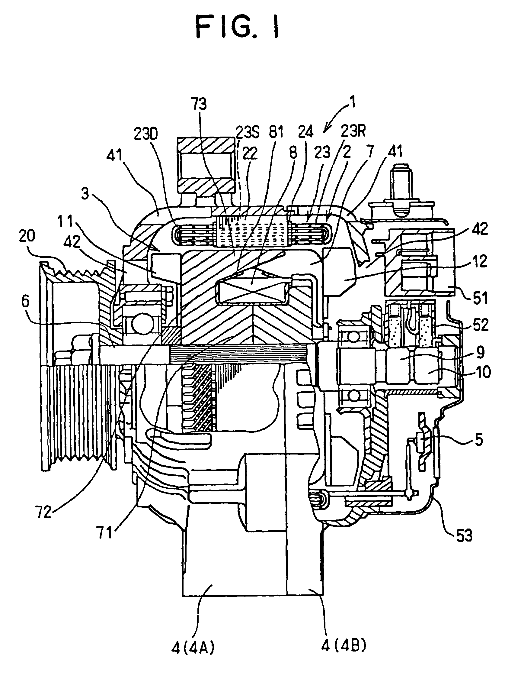
[0032]Referring to FIG. 1, the alternator 1 has a stator 2, a rotor 3, a frame 4 and a rectifier 5. The stator 2 is supported and fixed on the frame 4. The stator 2 has a stator core 22, a stator winding 23 and insulators 24 insulating the stator winding 23 from the stator core 22 as shown in FIG. 3. The stator core 22 is made of a laminated thin steel plate. The stator core 22 has a plurality of slots 25 that accommodate a part of the stator winding 23. The stator winding 23 provides drive side coil ends 23D and rear side coil ends 23R.

[0033]The stator winding 23 is a three-phase winding that is made of a plurality of conductors 230. Each of the phase windings has a pair of coils provided by conductors 230, respectively. Each of conductors 230 is a continuous wire and is wound to provide an individual coil wound at least one time around the sta...

second embodiment

[0061

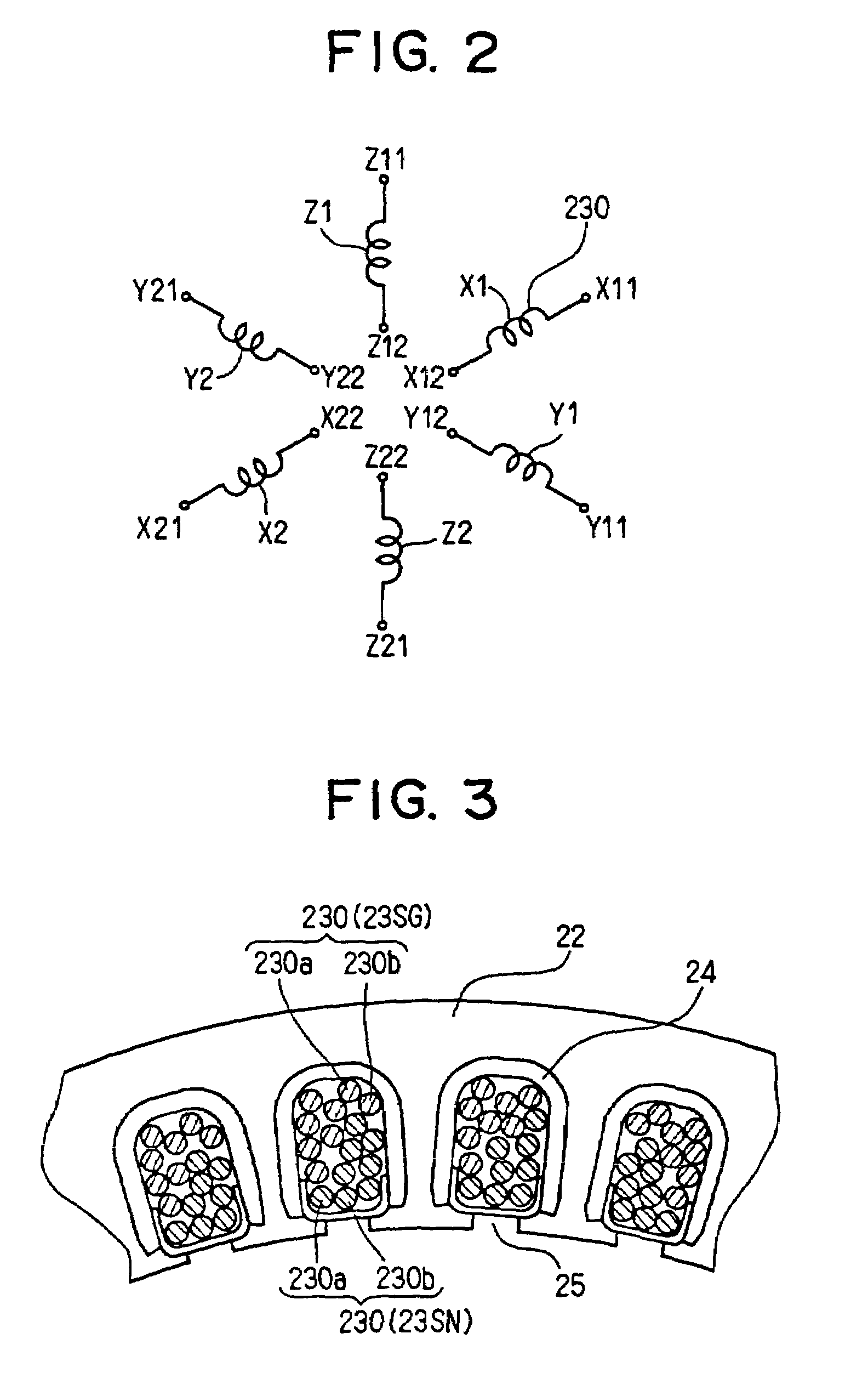
[0062]FIG. 10 shows a second embodiment of the present invention. In this embodiment, the stator winding 223 is provided by a plurality of lap-windings. Referring to FIGS. 10 and 11, the winding process begins from left and ends at right. In the winding process, the conductors 230 are wound on the tool in accordance with the order indicated in FIG. 11. For instance, the conductor 230 for the coil Z1 is placed on the inner in-slot portions SN1, the drive side coil ends D1, the outer in-slot portions SG4 and the rear side coil ends R1, during the first step to the 15th step. Therefore, the coil Z1 has four turn coils between the first to fourth slots. Then the conductor 230 is shifted three slots in the 16th step.

[0063]As a result, a belt-shaped coil is provided. The belt-shaped coil is curved and joined by overlapping at the left and right three slots. The coils X1, Y1, Z1, X2, Y2 and Z2 are connected into the Y-connection as shown in FIG. 12. In this embodiment, the coils X1 an...


PUM

PropertyMeasurementUnit
electric angleaaaaaaaaaa
diameteraaaaaaaaaa
electrical phasesaaaaaaaaaa

Abstract

A method for manufacturing rotary electric machine that has a stator winding to provide a stator winding that has a plurality of conductors wound one over another. The conductors are wound with left and right ends. Therefore, the stator winding on the stator core has an overlapped joined portion.

Description

[0001]This is a Division of Application Ser. No. 09 / 960,735 filed Sep. 24, 2001 now U.S. Pat. No. 6,727,625. The entire disclosure of the prior applications are hereby incorporated by reference herein in their entirety.CROSS REFERENCE TO RELATED APPLICATION[0002]This application is based on Japanese Patent Application No. 2000-290363 filed on Sep. 25, 2000, the contents of which are incorporated herein by reference.BACKGROUND OF THE INVENTION[0003]1. Field of the Invention:[0004]The present invention relates to a rotary electric machine and a method for manufacturing the same.[0005]2. Description of Related Art:[0006]JP-A-54-66406 discloses an AC rotary electric machine that has a plurality of coils. The coils are inserted into slots in orderly manner to provide short coil ends by preventing crossings of the coil ends. However, this arrangement forms larger space in the slots to prevent the crossings of the coil ends.[0007]JP-B-2927288 discloses an alternator for vehicle as a rotary...

Claims


Application Information

Patent Timeline
Patent Type & Authority Patents(United States)
IPC IPC(8): H02K15/04H02K15/06H02K15/085H02K3/04H02K3/28
CPCH02K3/28H02K15/0478Y10T29/53143Y10T29/49073Y10T29/49012Y10T29/49071Y10T29/49009
Inventor OOIWA, TOORU
Owner DENSO CORP
Why Eureka
Try Eureka