Disposable and trimmable wireless pressure sensor

a wireless pressure sensor and sensor technology, applied in the field of sensing devices and applications, can solve the problems of inability of conventional saw sensing systems to meet the demand in low pressure applications, inability to accurately sensing air pressure and temperature, and inability to accurately detect air pressure and temperatur

Inactive Publication Date: 2006-12-12
HONEYWELL INT INC
View PDF14 Cites 114 Cited by
  • Summary
  • Abstract
  • Description
  • Claims
  • Application Information

AI Technical Summary

Benefits of technology

[0013]The following summary of the invention is provided to facilitate an understanding of some of the innovative features unique to the present invention and is not intended to be a full description. A full appreciation of the various aspects of the invention can be gained by taking the entire specification, claims, drawings, and abstract as a whole.

Problems solved by technology

One of the problems with current SAW sensor designs, particularly those designs adapted to lower pressure range applications, is the inability of conventional SAW sensing systems to meet the demand in low pressure applications.
Such systems are inherently expensive, awkward, and often are not reliable in accurately sensing air pressure and temperature.
For example, an LC resonator (tank) sensor has the potential of being utilized as a low cost sensor with a low interrogation cost, but provides a relatively poor sensor performance.
An LC tank with regulated power, an associated ASIC and so forth has also been implemented, such a device may be good for multiple sensing applications, but such a configuration presents a high sensor cost and a large area coil.
PVDF acoustic wave sensors are also known and are based on low cost materials such as polymer along with flexible components thereof, but PVDF acoustic wave sensors are typically both piezo-electric and pyro-electric (i.e., highly temperature dependent), and cannot be exposed to temperatures greater than 120° C. Additionally the dimensions for a PVDF sensor are frequency dependent, such that the higher frequencies increase the associated costs to the sensor.
Another example of a conventional sensor is the magneto elastic sensor, which is based on a low cost material, but such a sensor has difficulties in overcoming ambient RF effects, while also possessing long term stability issues associated with permanent magnetic materials, temperature variation and hysteresis problems.
A further example of a passive sensor is a quartz SAW sensor, which is generally accurate but results in a high sensor cost (i.e., material and etching) and trimming thereof lowers the Q value, and hence the performance of the device.
Additionally the interrogation electronics (IE) for such a device can be expensive.
But it is difficult to control PZT chemistry (e.g., grain size, orientation, residual stress, control of nucleation at the at the electrode / PZT interface, Zr / Ti ratio control).
PZT SAW sensor devices are also plagued with issues related to electrode materials migration, another drawback to the use of such a device.
The LiNbO3 SAW sensor possesses a lower cost structure than the Quartz SAW sensor, but remains too high for cost-effective applications, particularly when considering its associated sensor packaging and interrogation electronics (IE) costs.
The relative position needs reference sensor, and therefore the alignment is difficult to control in sensing applications.
Another drawback to optical sensors is that such devices are susceptible to environmental interference.
To date, such components have not been adequately achieved.
Conventional pressure sensors are expensive to implement in medical applications, rendering their wide-spread use limited, particularly in medical applications.

Method used


Image

  • Disposable and trimmable wireless pressure sensor
  • Disposable and trimmable wireless pressure sensor
  • Disposable and trimmable wireless pressure sensor

Examples


Embodiment Construction

[0037]The particular values and configurations discussed in these non-limiting examples can be varied and are cited merely to illustrate at least one embodiment of the present invention and are not intended to limit the scope of the invention.

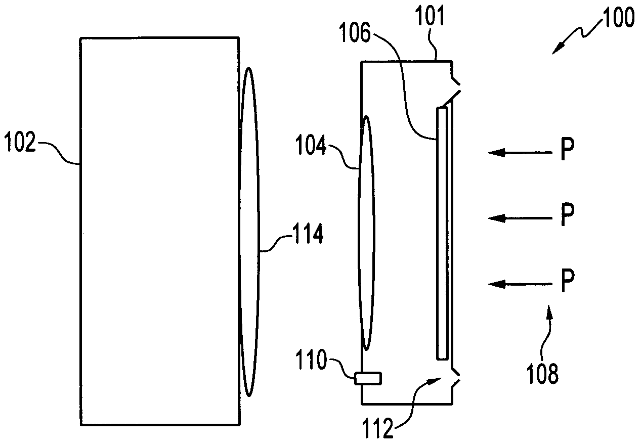
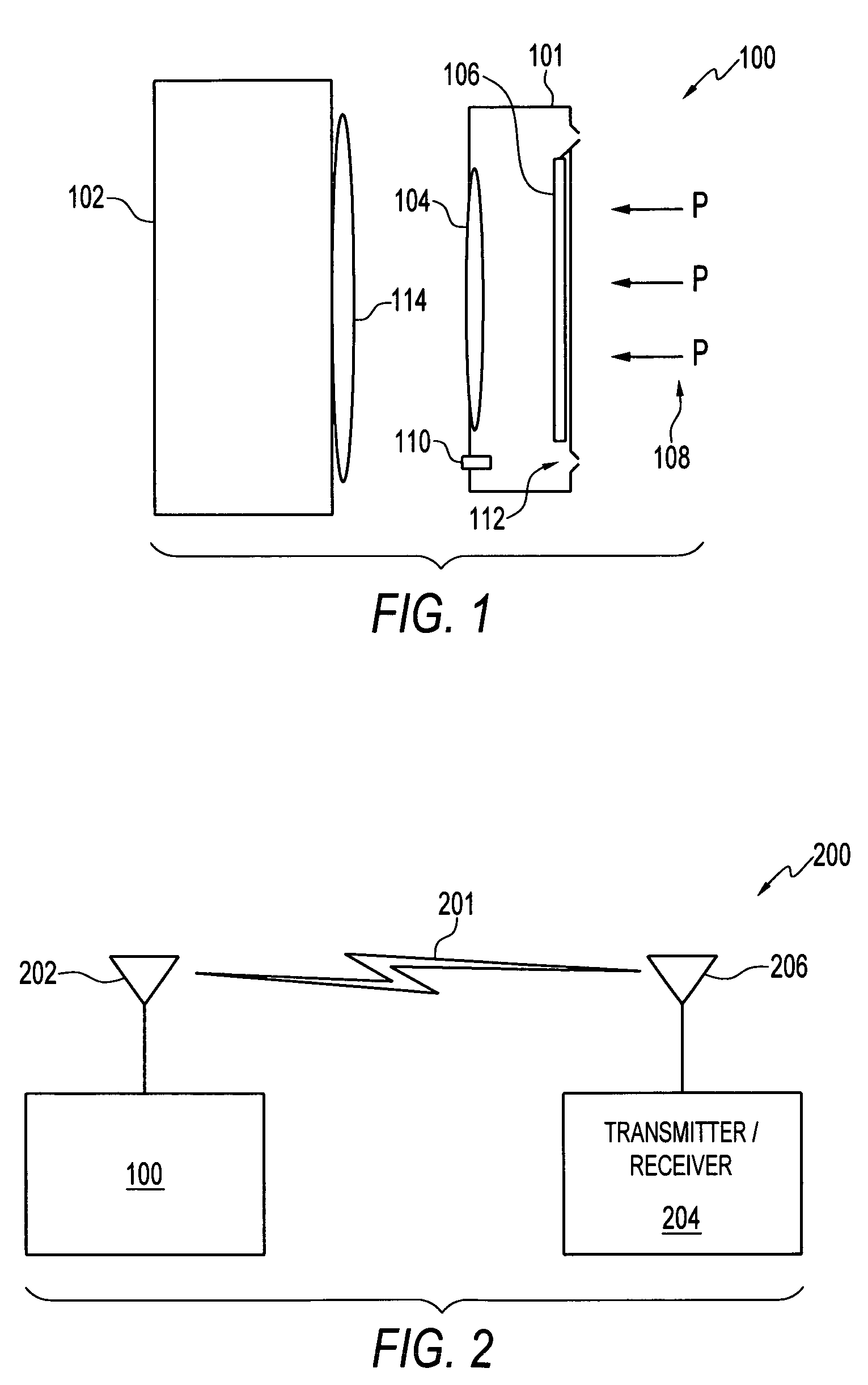
[0038]FIG. 1 illustrates a block diagram of a pressure sensor system, which can be implemented in accordance with a preferred embodiment. A substrate 101 can be provided upon which a capacitor 110 and an inductor 104 are fixed to the substrate 101 to form a pressure sensor thereof. The inductor 104 can be configured to comprise a planar inductor surface and one ferromagnetic pressure diaphragms 112, such that when the diaphragm 112 is exposed to a pressure as indicated by arrows 108, the diaphragm 112 moves close to the inductor surface, thereby resulting in an increase in the inductance and a decrease in the resonant frequency of the LC tank resonant circuit associated with the capacitor 110 and the inductor 104 and any associated circuitry th...


PUM

PropertyMeasurementUnit
temperaturesaaaaaaaaaa
frequencyaaaaaaaaaa
frequencyaaaaaaaaaa

Abstract

A disposable pressure sensor includes a substrate and a pressure diaphragm formed upon the substrate. A sensor coil can be provided, comprising a capacitor and an inductor formed on the substrate and surrounded by the pressure diaphragm. The ferrite core is located proximate to the sensor coil, such that when the pressure diaphragm is exposed to a pressure, the diaphragm moves close to the inductor or the capacitor, thereby resulting in a change in the capacitor or the inductor and an indication of pressure. The capacitor can be implanted as an adjustable, trimmable or variable capacitor. The inductor may also be provided as an adjustable or variable inductor and can include the use of a variable capacitor and a PVDF based piezoelectric transducer. When the PVDF layer is under pressure, it can generate an electric field across the interdigital transducer and transmit a signal thereof through an antenna.

Description

TECHNICAL FIELD[0001]Embodiments are generally related to sensing devices and applications. Embodiments are also related to pressure sensor devices, systems and methods thereof. Embodiments are additionally related to low cost disposable sensing devices.BACKGROUND OF THE INVENTION[0002]A variety of sensors can be utilized to detect conditions, such as pressure and temperature. The ability to detect pressure and / or temperature is an advantage to any device exposed to variable pressure conditions, which can be severely affected by these conditions. An example of such a device is a catheter or a cartridge for hemodialysis machine, which of course, can experience variations in both temperature and pressure. Many different techniques have been proposed for sensing the pressure and / or temperature in catheters and cartridges, and for delivering this information to an operator so that he or she is aware of pressure and temperature conditions associated with a catheter or a cartridge and any...

Claims


Application Information

Patent Timeline
Patent Type & Authority Patents(United States)
IPC IPC(8): G01L9/12
CPCA61B5/0215G01D21/00G01L9/0025G01L9/007G01L9/0072G01L9/008G01L9/08G01L9/10G01L9/12G01D5/185
Inventor COOK, JAMES D.LIU, JAMES ZT
Owner HONEYWELL INT INC
Why Eureka
Try Eureka