Method and system for nitrifying and denitrifying wastewater

a wastewater and denitrification technology, applied in the field of wastewater treatment, can solve the problems of compromising the denitrification rate and overall effectiveness of the denitrification process, difficult nitrogen removal for municipalities and sewer authorities, and difficult to achieve cost-effective and efficient nitrogen removal in a cost-effective manner, so as to reduce or minimize the dissolved oxygen concentration, reduce or minimize the effect of dissolved oxygen concentration

Active Publication Date: 2006-12-12
KRUGER I INC
View PDF27 Cites 111 Cited by
  • Summary
  • Abstract
  • Description
  • Claims
  • Application Information

AI Technical Summary

Benefits of technology

[0008]The present invention entails a process for nitrifying and denitrifying wastewater and reducing or minimizing the dissolved oxygen concentration in a denitrification zone during the process. Wastewater influent is alternatively directed to first and second zones. At various times during the process the first zone is maintained as a nitrification zone and the second zone is maintained as a denitrification zone. At other times the first zone is maintained as a denitrification zone and the second zone is maintained as a nitrification zone. Alternatively, wastewater or mixed liquor in the first and second zones is directed to a downstream aerobic reactor having one or more immersed membranes contained therein. The downstream aerobic reactor is aerated. Wastewater or mixed liquor in the aerobic reactor is directed into one or more immersed membranes for separating the wastewater into permeate and return activated sludge. The permeate is pumped from the one or more immersed membranes. The resulting activated sludge in the aerobic reactor is returned to either the first or second zones. The process reduces or minimizes the dissolved oxygen concentration in the denitrification zones by selectively directing the return activated sludge to the first or second zone being maintained as a nitrification zone and switching the flow of the return activated sludge during the process between the first and second zones so as to direct the return activated sludge to the zone being maintained as a nitrification zone.
[0009]Further, the present invention entails a process for not only performing nitrification and denitrification, but also phosphorus removal. In this case, an anaerobic reactor is placed upstream from the first and second zones that are alternatively utilized as nitrification and denitrification zones. In this case, return activated sludge is directed from the downstream aerobic reactor having the one or more immersed membranes to either the first or second zone being maintained under aerobic conditions for purposes of nitrification. To effectively remove phosphorus from the wastewater, the wastewater or mixed liquor in the first or second zones being maintained under anoxic or denitrifying conditions is recycled to the anaerobic zone containing one or more reactors. Hence, the process is effective for both nitrification-denitrification and biological phosphorus removal.

Problems solved by technology

Nitrogen removal is a difficult problem facing municipalities and sewer authorities throughout the world.
While there has been significant advancement in nitrogen removal through biological treatment, efficient and effective nitrogen removal in a cost effective manner remains challenging.
In the anoxic reactor, the desired electron acceptor is nitrate and the presence of other electron acceptors, such as oxygen (O2) will compromise the denitrification rate and the overall effectiveness of the denitrification process.
The immersed membranes are subject to fouling due to a biomass concentration gradient produced by the flux and the subsequent accumulation and dewatering mechanism acting on the solids.
The high air scour flow rate required to effectively scour the membranes often results in a local high dissolved oxygen concentration, which is then recycled to the anoxic reactor along with the recycled biomass or sludge.
Since the volume, and detention time, of the anoxic reactor is small compared to that of the aerobic treatment reactors and zone, and recirculation rates are high (2 to 5 times influent flow rates), the high dissolved oxygen concentration in the recycled stream cannot be adequately reduced.

Method used


Image

  • Method and system for nitrifying and denitrifying wastewater
  • Method and system for nitrifying and denitrifying wastewater
  • Method and system for nitrifying and denitrifying wastewater

Examples


Embodiment Construction

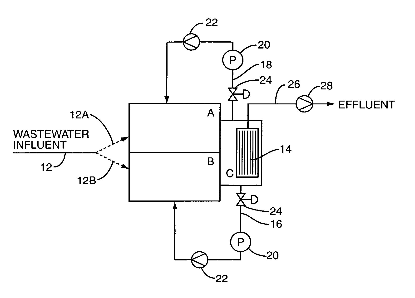
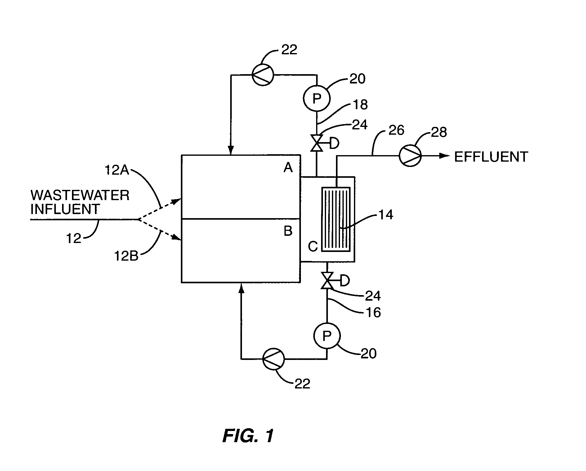
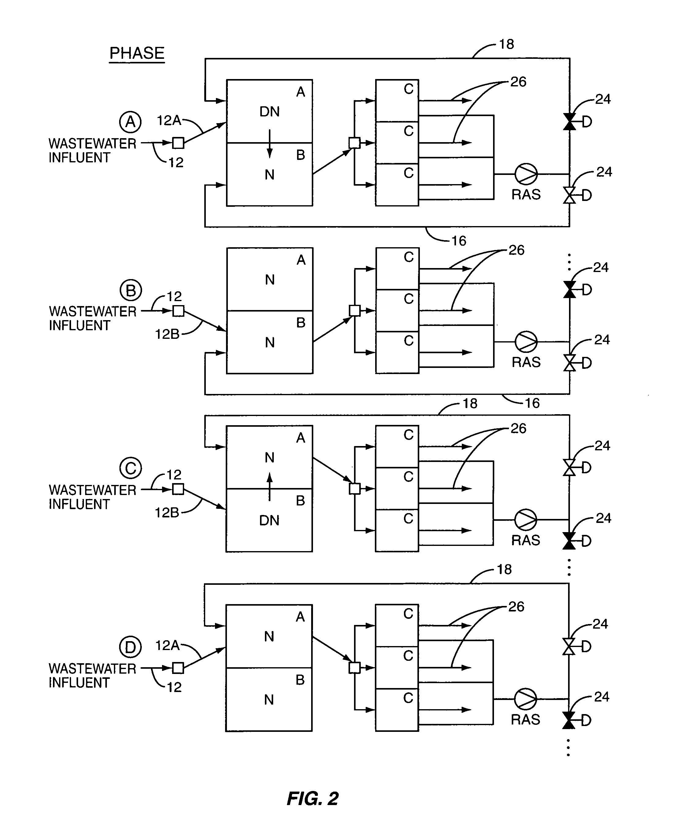
[0014]Typically, wastewater influent includes ammonia nitrogen, NH3—N. To remove ammonia nitrogen, a two-step process is called for, nitrification and Denitrification. First, the nitrification step entails converting the ammonia nitrogen (NH3—N) to nitrate and a very small amount of nitrite, both commonly referred to as NOx. There are a number of conventional processes that can be utilized in a nitrification process. For example, many conventional activated sludge wastewater treatment processes accomplish nitrification in an aerobic treatment zone. In an aerobic treatment zone the wastewater containing the ammonia nitrogen is subjected to aeration and this gives rise to a microorganism culture that effectively converts the ammonia nitrogen to NOx. Once the ammonia nitrogen has been converted to NOx, then the NOx containing wastewater is typically transferred to an anoxic zone for the purpose of denitrification. In the denitrification treatment zone, the NOx containing wastewater is ...


PUM

PropertyMeasurementUnit
detention timeaaaaaaaaaa
time durationaaaaaaaaaa

Abstract

A wastewater treatment system is provided that includes first and second reactors, each operative to nitrify or denitrify wastewater contained therein. Downstream from the first and second reactors is a membrane reactor that operates under aerobic conditions and includes one or more submersed membranes for separating solids. Extending between the membrane reactor and each of the first and second reactors is a return activated sludge line with appropriate controls for permitting return activated sludge to be directed to one of the reactors at a time. To nitrify and denitrify wastewater, a wastewater influent stream is alternatively directed to the anoxic reactors which are alternatively operated under aerobic and anoxic conditions so as to nitrify or denitrify the wastewater contained therein. To reduce or minimize the dissolved oxygen return from the membrane reactor to the first and second reactors, the flow of return activated sludge is controlled such that generally return activated sludge is returned to the reactor operating under aerobic conditions.

Description

FIELD OF THE INVENTION[0001]The present invention relates to wastewater treatment, and more particularly to a system for nitrifying and denitrifying wastewater.BACKGROUND OF THE INVENTION[0002]Nitrogen removal is a difficult problem facing municipalities and sewer authorities throughout the world. While there has been significant advancement in nitrogen removal through biological treatment, efficient and effective nitrogen removal in a cost effective manner remains challenging. This is especially true in view of low nitrogen limits now being promulgated by many municipalities and governmental bodies.[0003]In its basic form, nitrogen removal is a two-step process that entails nitrification and denitrification. The nitrification process is carried out under aerobic conditions and involves the oxidation of nitrogen in the form of ammonia so as to form nitrate. The nitrification process is represented as follows:[0004]NH3+CO2+O2⁢→bacteria⁢⁢NO3+new⁢⁢bacteria[0005]Denitrification, on the ...

Claims


Application Information

Patent Timeline
Patent Type & Authority Patents(United States)
IPC IPC(8): C02F3/30
CPCC02F3/121C02F3/1263C02F3/1268C02F3/301C02F3/302Y10S210/903Y10S210/906Y02W10/10
Inventor DIMASSIMO, RICHARD W.HONG, SUN-NANZHAO, HONGWOOD, LUTHER
Owner KRUGER I INC
Why Eureka
Try Eureka