UV visual light beam combiner

a combiner and light beam technology, applied in the direction of optical radiation measurement, x-ray tubes, lenses, etc., can solve the problems of filter wheels, scanning diffraction gratings sensitive to vibration, and general inability to reliably analyze samples

Active Publication Date: 2006-12-12
OCEAN OPTICS
View PDF7 Cites 11 Cited by
  • Summary
  • Abstract
  • Description
  • Claims
  • Application Information

AI Technical Summary

Benefits of technology

[0010]This invention is an improved light beam combiner that creates a more uniform light source across the UV, Visual, and NIR range. It is an optical mechanical device made up of a standard high low dielectric thin film which, when placed at a 45 degree angle between a Deuterium lamp and a Tungsten or Halogen lamp reflects the UV portion of a Deuterium lamp and passes the visual portion while also allowing the visual energy of a Halogen / Tungsten lamp to pass resulting in a more uniform light source for use in spectroscopy.
[0012]It is yet another object of this invention to use one or more filters between the deuterium lamp and the beam combiner in order to further strip the visual signal out of the deuterium lamp. Further, it is another object of this invention to include variable attenuation of the halogen lamp which provides additional control of the system and facilitates precision tuning of the system.

Problems solved by technology

Based on moving parts, filter wheels and scanning diffraction gratings are sensitive to vibration and are not reliable in analyzing a sample generally.
They therefore are not suitable for withstanding the mechanical vibrations generated by machinery, and therefore have not found use in real-time measurements of samples other than in controlled laboratories.
Illuminating a sample with a highly intense incident light typically results in a greater amount of reflected light that is more easily measured by a detection device, which is often limited in sensitivity.
This often has a devastating impact on measurement accuracy.
These problems have been addressed by numerous prior art devices that have greatly advanced the dependability and accuracy of spectroscopy but none have disclosed the mechanical optical light beam combiner of this application.
The U.S. Pat. No. 6,256,700 patent discusses an extensive overview of light sources, or light engines for various purposes, but does not disclose the unique mechanical optical design of this application.
The devices of the prior art patents are for projection systems and are not intended for spectral illumination of a target substance using two light sources.

Method used


Image

  • UV visual light beam combiner
  • UV visual light beam combiner
  • UV visual light beam combiner

Examples


Embodiment Construction

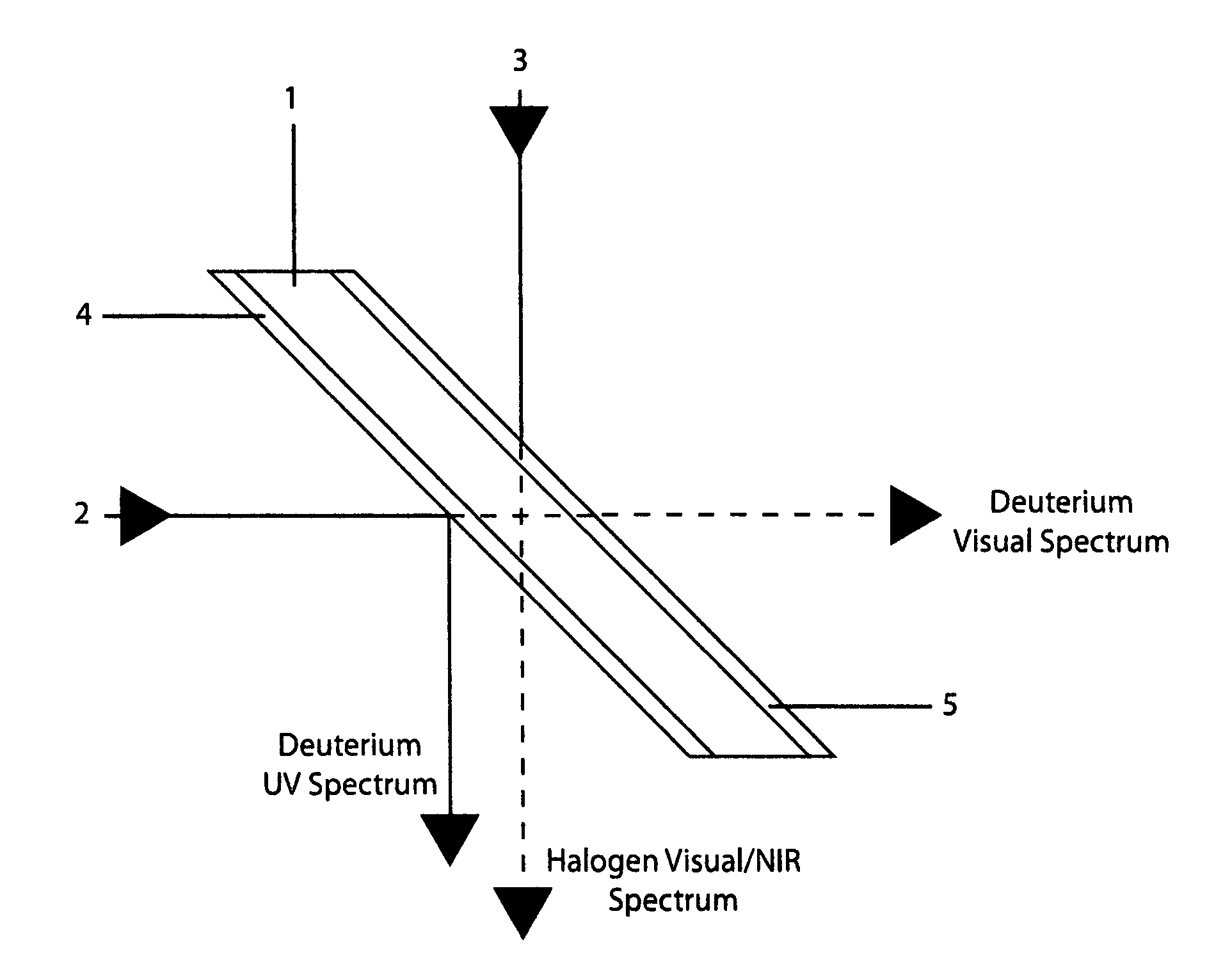
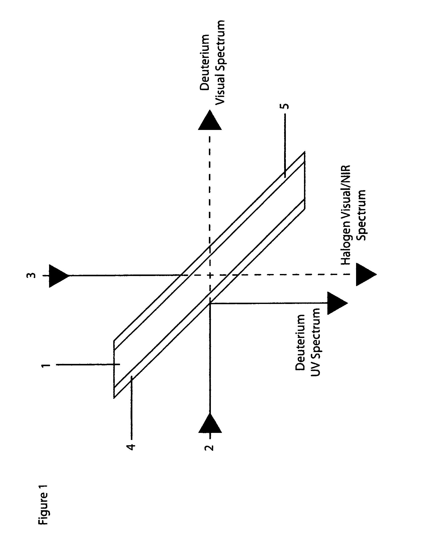
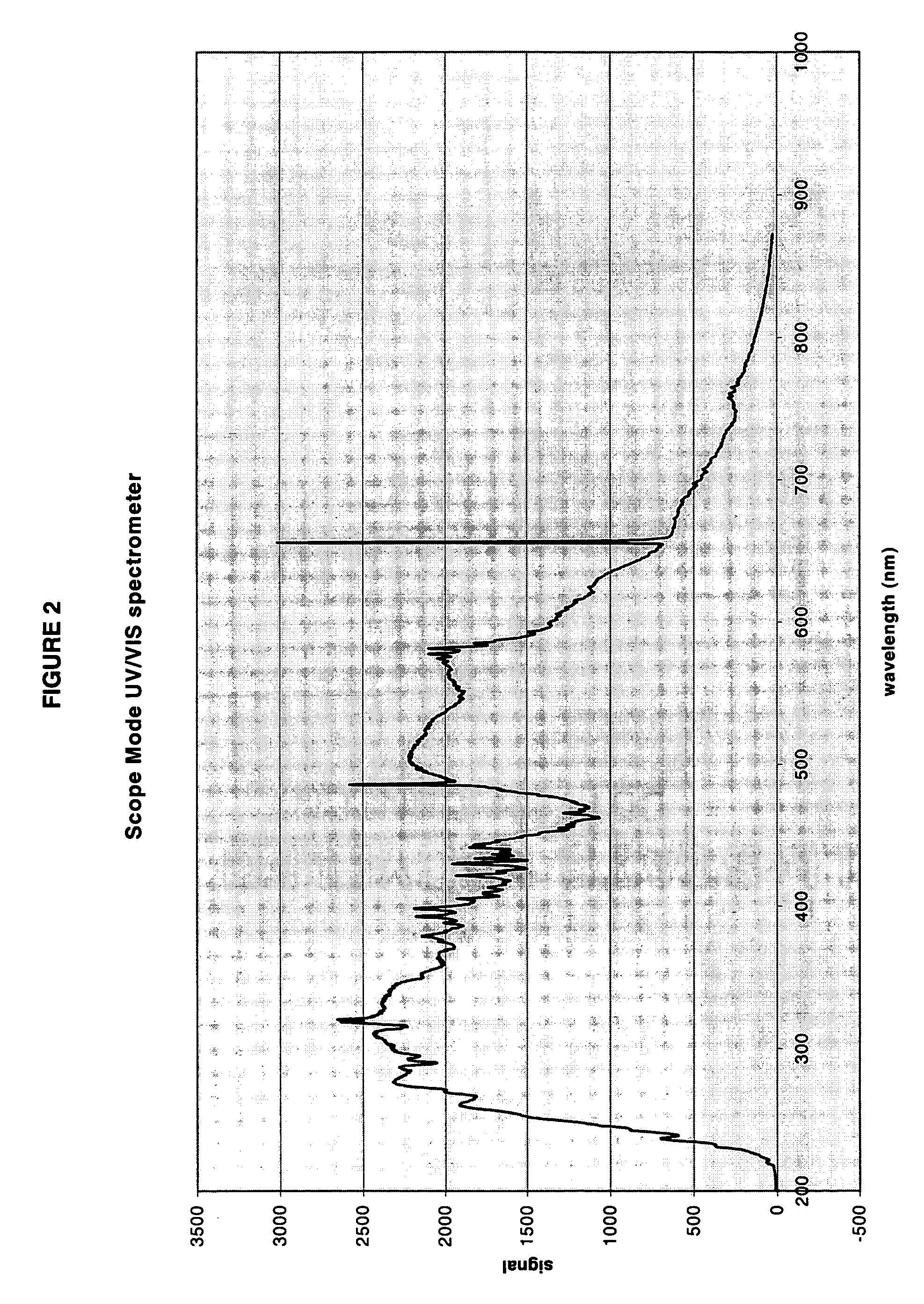
[0018]Referring now to FIG. 1, it will there be seen that the novel assembly is a simple mechanical optical device. The light beam combiner is based on a standard high low index dielectric thin film well known to those skilled in the art. In the preferred embodiment shown in FIG. 1 the film is coated on a transparent optical structure, such as clear glass, to create the filter element (1). This filter element (1) is then mounted, in any conventional manner known to those skilled in the art, at a forty-five degree (45°) angle to two light sources, a Deuterium lamp (2) and a Halogen or Tungsten lamp (3). In this configuration the filter element (1) reflects the UV wavelength portion of the Deuterium lamp (2) and passes the visual wavelength portion while allowing the visual wavelength portion of the Halogen / Tungsten (3) to pass through thus resulting in a more uniform light source across the UV, visual, and near infra-red spectrum. This result is more clearly shown in the spectrum ana...


PUM


Abstract

An improved light beam combiner is disclosed that creates a more uniform light source across the UV, Visual, and NIR range. It is an optical mechanical device made up of a standard high low dielectric thin film which, when placed at a 45 degree angle between a Deuterium lamp and a Halogen or Tungsten lamp, reflects the UV portion of a Deuterium lamp and passes the visual portion while also allowing the visual energy of a Halogen or Tungsten lamp to pass resulting in a more uniform light source for use in spectroscopy.

Description

FIELD OF THE INVENTION[0001]This invention relates, generally, to an improved Light Beam Combiner that creates a more uniform light source across the UV, Visual, and NIR range. More specifically it is an optical mechanical device which reflects the UV portion of a Deuterium lamp and passes the visual portion while allowing the visual energy of a Halogen or Tungsten lamp to pass giving a more uniform light source for use in spectroscopy.BACKGROUND OF THE INVENTION[0002]Spectral analyzers have long gained favor because they provide a fast and non-destructive means of analyzing different types of samples. Based on this technology, it is possible not only to determine the characteristics of a sample surface, but sometimes the constituent components beneath a sample surface. Typically, an optimal range of wavelengths is selected to irradiate a sample, where reflected or transmitted light is measured to determine the characteristics of the sample. Some samples, for example, are best analy...

Claims


Application Information

Patent Timeline
Patent Type & Authority Patents(United States)
IPC IPC(8): G02B27/10A61B1/06G02B13/00G02B27/14H04N7/18
CPCG01J3/10
Inventor BUCHSBAUM, PHILIP E.
Owner OCEAN OPTICS
Why Eureka
Try Eureka