Control system for mobile NOx SCR applications

a control system and mobile technology, applied in the direction of exhaust treatment electric control, separation process, instruments, etc., can solve the problems of limiting the amount of nitrogen oxides that can be emitted, difficult catalytic reduction of nitrogen oxides, and insufficient combustion and engine modifications to meet the more stringent levels

Inactive Publication Date: 2006-12-19
ENGELHARD CORP
View PDF29 Cites 104 Cited by
  • Summary
  • Abstract
  • Description
  • Claims
  • Application Information

AI Technical Summary

Benefits of technology

[0078]FIG. 9 is a graph of an ETC test plotting the functional catalyst temperature predicted by the invention, the sensed mid-bed catalyst temperature and the sensed average catalyst temperature;
[0079]FIG. 10 is a schematic representation of the TCat filter of the present invention in a discrete form;
[008...

Problems solved by technology

Unfortunately, the presence of excess air makes the catalytic reduction of nitrogen oxides difficult.
The regulations are increasingly limiting the amount of nitrogen oxides that can be emitted during the regulated drive cycle.
Projected emission levels are such that combustion and engine modifications will not be sufficient to meet the more stringent levels.
Because of excess oxygen present in diesel exhaust gases, the opportunity for NOx reduction under rich or stoichiometric air/fuel is not possible.
Unfortunately, as of this date, an HC reducing catalyst has not yet been developed which has sufficient activity and is effective over the entire operating range of the diesel engine.
Notwithstanding what may be said to be inherent advantages of an ammonia based SCR system, the control systems to date have been excessively complicated and/or ineffective to control the SCR system when the impact of NOx transient em...

Method used


Image

  • Control system for mobile NOx SCR applications
  • Control system for mobile NOx SCR applications
  • Control system for mobile NOx SCR applications

Examples


Embodiment Construction

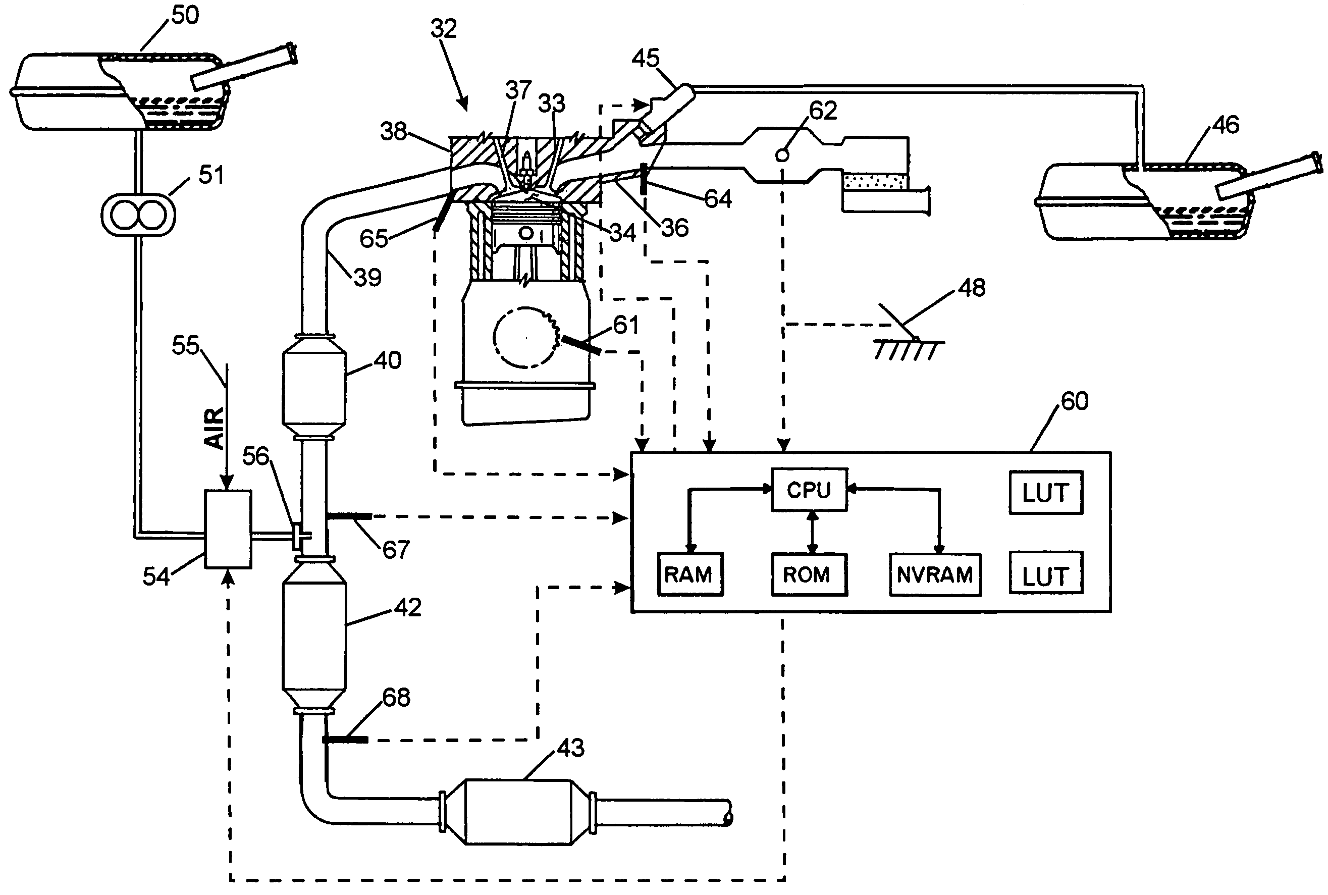
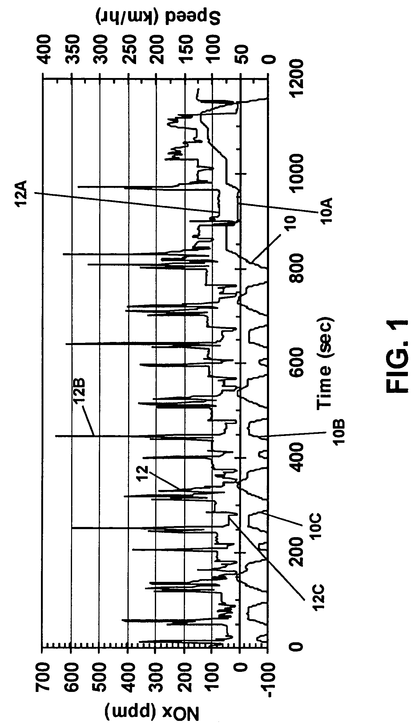
[0082]Referring now to the drawings wherein the showings are for the purpose of illustrating a preferred embodiment of the invention only and not for the purpose of limiting the same, there is shown in FIG. 1 an MVEG test conducted with a test vehicle equipped with a 1.9 liter turbocharged, direct injection (TDI) diesel engine, i.e., a light duty test vehicle. The invention will be described throughout as applicable to a diesel engine, but as indicated above, the invention, in its broader sense, is applicable to any internal combustion (IC) engine, such as gasoline fuel type engines operated lean or with “lean burn” engine fuel strategy.

[0083]In FIG. 1, the European MVEG cycle is plotted in seconds on the x-axis with the nitrogen oxides (NOx) emitted by the vehicle during the drive cycle plotted on the left-hand y-axis and the vehicle speed plotted in km / hr on the right-hand y-axis. The lower trace identified by the reference numeral 10 is a plot of the vehicle speed over the timed ...


PUM


Abstract

A diesel powered vehicle is provided with an SCR system which uses an external reducing reagent to convert NOx emissions in a manner which accounts for the effects of NOx transient emissions on the reducing catalyst. Actual NOx emissions produced by the engine are filtered using a variable NOx time constant in turn correlated to the reductant/NOx storage capacity of the reducing catalyst at its current temperature to account for changes in the SCR system attributed to NOx transient emissions. Catalyst temperature is filtered using a variable catalyst time constant corresponding to current space velocity of the exhaust gas to account for changes in the catalyst temperature attributed to NOx transient emissions. The reductant is metered on the basis of the filtered, corrected NOx concentration applied at a NSR ratio based, in turn, on the filtered, corrected reducing catalyst temperature.

Description

[0001]This invention relates generally to nitrogen oxide (NOx) emissions produced by internal combustion engines in a vehicle and more particularly to a system for controlling reduction of the NOx emissions by means of a selective catalytic reduction (SCR) method.[0002]The invention is particularly applicable to and will be described with specific reference to a control system for regulating the supply of an external reductant, ammonia, to a reducing catalyst in an SCR system taking into account the effect of NOx transient emissions produced in vehicles powered by diesel engines. However, those skilled in the art will recognize that the control system has broader applications and may be applied to SCR systems using other reductants such as fuel oil or hydrocarbons as well as SCR systems used in other mobile internal combustion engine applications, such as gasoline engines employing “lean burn” techniques.INCORPORATION BY REFERENCE[0003]The following patents and publications are inco...

Claims


Application Information

Patent Timeline
IPC IPC(8): F01N3/00F01N3/08B01D53/56B01D53/74B01D53/90B01D53/94F01N3/20F01N3/28F01N9/00
CPCB01D53/90B01D53/9431B01D53/9495F01N3/103F01N3/208F01N9/005F01N13/009F01N5/02F01N2570/18F01N2610/02F01N2610/08F01N2610/12F01N2900/0404F01N2900/14F01N2900/1402F01N2900/1622F01N2900/1808Y02T10/47Y02T10/24Y02A50/20Y02T10/12Y02T10/40F01N3/20
Inventor PATCHETT, JOSEPH A.VERBEEK, RUDOLFUS PETRUSGRIMSTON, KARL RICHARDRICE, GARY WAYNECALABRESE, JOHN LAWRENCEVAN GENDEREN, MATHUS
Owner ENGELHARD CORP
Why Eureka
Try Eureka