Variable spot size illuminator having a zoom lens

a technology of variable spot size and zoom lens, which is applied in the field of variable spot size illuminator, can solve the problems of lower laser spot intensity variation

Active Publication Date: 2006-12-19
ALCON INC
View PDF18 Cites 10 Cited by
  • Summary
  • Abstract
  • Description
  • Claims
  • Application Information

AI Technical Summary

Benefits of technology

[0016]In other aspects, the invention provides a variable spot size illuminator that provides a light spot on a treatment plane with parfocality. Similar to the illuminators of the invention described above, such an illuminator includes a radiation source that can generate, for example, a beam of light, and a focusing lens system that is optically coupled to the light source in order to generate an image of the light beam on an intermediate plane. The illuminator can further include a zoom lens disposed between the intermediate plane and a treatment plane to direct a beam of light received from the intermediate image onto the treatment plane in order to form a treatment light spot thereon. The zoom lens is designed such that a diameter of the beam directed by the zo

Problems solved by technology

Such a mode scrambler will also significantly lower the laser spot's intensity var

Method used


Image

  • Variable spot size illuminator having a zoom lens
  • Variable spot size illuminator having a zoom lens
  • Variable spot size illuminator having a zoom lens

Examples


Embodiment Construction

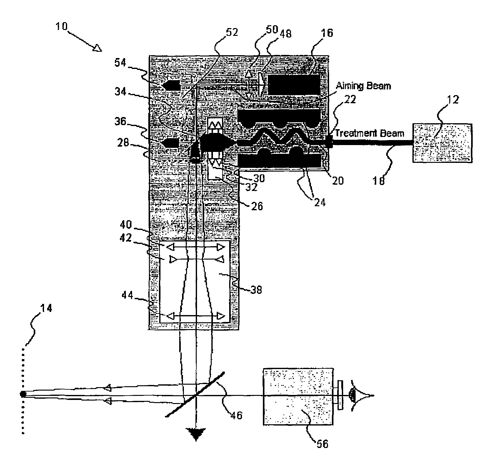
[0025]The present invention provides a variable spot-size illuminator that images a treatment beam on an intermediate plane, and utilizes a zoom lens system to re-image the image formed on the intermediate plane onto the treatment plane at a selected magnification. The illuminator further includes an annular aiming beam that can propagate coaxially with the treatment beam to allow positioning the treatment beam on an outlined portion of an illumination / treatment plane.

[0026]More particularly, FIG. 1 schematically illustrates an exemplary variable spot size illuminator 10 according to the teachings of the invention that employs a treatment light beam provided by a treatment radiation source 12, such as a laser, to generate a treatment spot on a treatment plane 14, as described in detail below, and further employs an aiming beam provided by an aiming light source 16, e.g., another laser operating at a different wavelength, to direct the treatment spot to a desired location on the trea...


PUM


Abstract

The present invention provides variable spot size illuminators that provide a light spot on a treatment plane by utilizing a zoom lens to direct light received from an image of a light source formed on an intermediate image plane onto the treatment plane. The zoom lens allows varying the size of the treatment spot while ensuring that the treatment spot exhibits parfocality. An illuminator of the invention can be utilized for performing a number of ophthalmic surgical procedures, such as, photocoagulation, transpupillary thermal therapy, and photodynamic therapy.

Description

BACKGROUND OF THE INVENTION[0001]The present invention relates generally to variable spot size illuminators, and more particularly, to such illuminators that can provide a homogeneous illumination spot whose size can be continuously varied while exhibiting parfocality.[0002]A number of ophthalmic surgical procedures performed on a patient's retina require illuminating a selected portion of the retina with an illumination spot, typically provided by a laser, having a desired size. For example, in one such surgical procedure, known as photocoagulation, a laser light spot is directed to a selected portion of a patient's retina to cause coagulation of the illuminated tissue by generating heat. Photocoagulation can be employed, for example, to seal leaky blood vessels, destroy abnormal blood vessels, or heal retinal detachment.[0003]In another ophthalmic surgical procedure, commonly known as photodynamic therapy, an agent, which is inert in the absence of light activation, is initially a...

Claims


Application Information

Patent Timeline
IPC IPC(8): A61B3/10A61B17/00A61B18/20A61F9/008A61N5/06
CPCA61F9/008A61F9/00821A61B18/20A61B2017/00057A61B2018/00636A61F2009/00844A61F2009/00863A61N5/062
Inventor ARTSYUKHOVICH, ALEXANDER N.LASSALAS, BRUNO X.ROWE, T. SCOTTFINK, MARKFISCHER, ROBERT E.
Owner ALCON INC
Why Eureka
Try Eureka