Printing form and method for modifying its wetting properties

a technology of wetting properties and printing forms, applied in the field of printing forms, can solve the problems of limited printing forms produced in accordance with this method

Inactive Publication Date: 2006-12-26
HEIDELBERGER DRUCKMASCHINEN AG
View PDF12 Cites 5 Cited by
  • Summary
  • Abstract
  • Description
  • Claims
  • Application Information

AI Technical Summary

Benefits of technology

[0006]An object of the present invention is to propose an alternative printing form having regions of higher hydrophobicity or regions in a strongly hydrophobic state, and to provide a method for locally and repeatedly modifying their wetting properties.

Problems solved by technology

A printing form produced in accordance with this method is limited by the minimum size of the crystalline regions.

Method used


Image

  • Printing form and method for modifying its wetting properties
  • Printing form and method for modifying its wetting properties
  • Printing form and method for modifying its wetting properties

Examples


Embodiment Construction

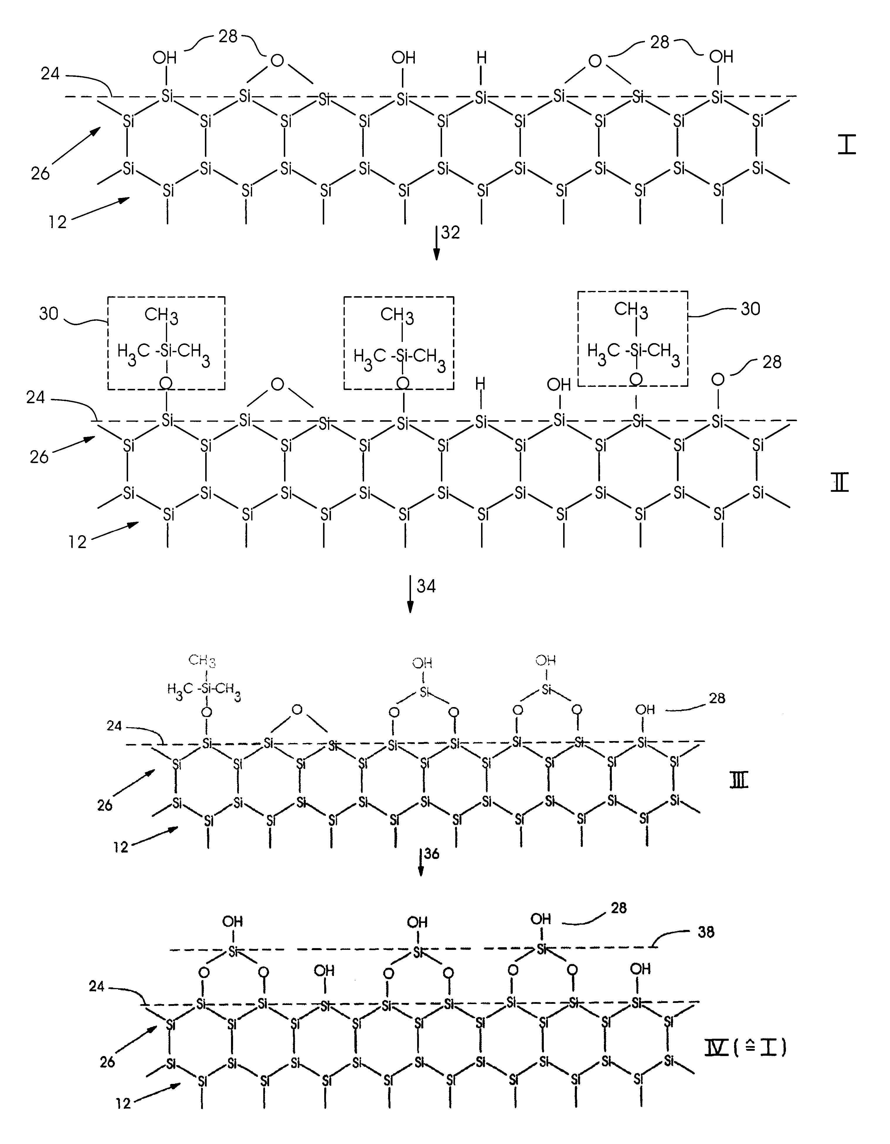
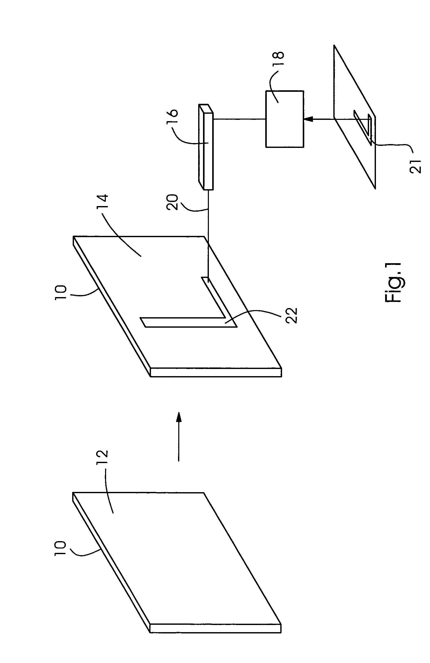
[0036]In FIG. 1, the method according to the present invention is schematically shown. A printing form 10 has a plate-shaped design and may be accommodated on a printing-form cylinder, in particular in a printing press. Printing form 10 has a surface 12 which has inorganically bonded silicon. In its original state, especially following its manufacturing process, this printing form 10 is typically covered with a native oxide layer having a thickness of a few nanometers.

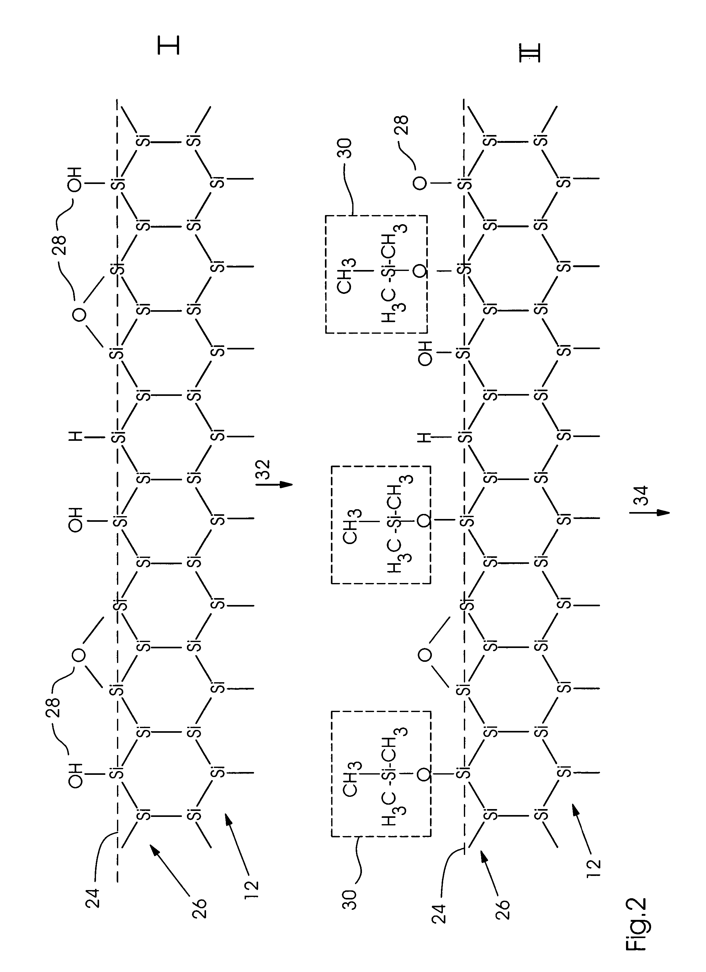
[0037]In a first method step according to the present invention, printing form 10 is provided with a defined, substantially hydrophobic surface. For this purpose, surface 12 of printing form 10 is terminated using organic terminal groups or fluorinated organic terminal groups. The free valences of the silicon surface atoms are saturated by the corresponding terminal groups, in particular aryl terminal groups, alkyl terminal groups or fluoralkyl terminal groups.

[0038]At this point, hydrophobic region 14 of printing form...


PUM

PropertyMeasurementUnit
thicknessaaaaaaaaaa
thicknessaaaaaaaaaa
wavelengthaaaaaaaaaa

Abstract

A printing form (10) having a surface (12) of pure silicon or of a silicon ceramic, which bears a pattern composed of hydrophilic and hydrophobic regions, the hydrophilic regions having a first chemical state and the hydrophobic regions having a second chemical state that differs from the first chemical state, in hydrophobic regions, the surface (12) having silicon atoms, to which at least one organic terminal group is attached in each instance. The organic terminal group may be, in particular, an unsubstituted or halogenated aryl terminal group or alkyl terminal group and be attached via an Si—C, Si—O—C or Si—O—Si—C bond. Also a method for modifying the wetting properties of the printing form, the surface (12) being brought into a first chemical state having a first wetting property, and a portion of all regions of the surface (12) being brought into a second chemical state having a second wetting property by modifying the chemical terminal groups of the surface (12).

Description

[0001]This claims priority to German Patent Application No. 102 60 114.3 filed Dec. 19, 2002 and U.S. Provisional Patent Application No. 60 / 438,674 filed Jan. 8, 2003, both of which are hereby incorporated by reference herein.BACKGROUND[0002]The present invention is directed to a printing form having a surface which has inorganically bonded silicon and a pattern composed of hydrophilic and hydrophobic regions, the hydrophilic regions having a first chemical state and the hydrophobic regions having a second chemical state that differs from the first state. The present invention is also directed to a method for modifying the wetting properties of a printing form having a surface which has inorganically bonded silicon, the surface being brought into a first chemical state having a first wetting property, and a portion of all regions of the surface being brought into a second chemical state having a second wetting property by modifying the chemical terminal groups of the surface.[0003]F...

Claims


Application Information

Patent Timeline
Patent Type & Authority Patents(United States)
IPC IPC(8): B41N1/14B41C1/10B41N1/00
CPCB41C1/1041B41N1/006
Inventor SCHMOHL, ANDREASHESS, PETER
Owner HEIDELBERGER DRUCKMASCHINEN AG
Why Eureka
Try Eureka