Method and apparatus for determining urea concentration

a technology of urea concentration and method, applied in the direction of material electrochemical variables, instruments, and investigation of phase/state change, etc., can solve the problems of inability to selectively determine a urea concentration, affecting the correct determination of urea concentration, and requiring additional work in the creation of calibration curves

Active Publication Date: 2006-12-26
TOYO ENG CORP
View PDF15 Cites 28 Cited by
  • Summary
  • Abstract
  • Description
  • Claims
  • Application Information

AI Technical Summary

Benefits of technology

[0012]After intense investigation, the inventors have found that the above-identified problems may be solved by heating an aqueous solution containing urea under increased pressure, thereby hydrolyzing urea in the solution. The urea concentration is then determined using the electric conductivity of the solution containing hydrolysis products including ammonia, which is proportional to the contents of solutes, such as ammonia. The inventors have also found that when an aqueous solution to be measured contains a substance, such as ammonia, which may change electric conductivity, the above problems may be solved by measuring electric conductivity before and after hydrolysis of urea, respectively, and determining a urea concentration in the solution from the difference between these electric conductivities.

Problems solved by technology

However, due to a flaw in the colorimetry measurement system, subtle turbidity in a sample may disturb correct determination of the urea concentration using colorimetric determination method.
One drawback of this method is that a nitrogen analyzer determines a total nitrogen content in the measuring sample, and cannot selectively determine a urea concentration.
The creation of the calibration curve requires additional work, and may introduce inaccuracies from the operator's calculations.
Moreover, it is difficult to quickly determine only a urea concentration in a solution in which urea and ammonia coexist using the above-described techniques.
However, a decomposition state (a decomposition rate) for urea may vary depending on enzyme activity and may be susceptible to temperature changes at the place where the membrane is fixed.
Much maintenance effort is, therefore, required for keeping higher measuring precision.
Furthermore, due to membrane deterioration over time, the membrane must be replaced, leading to troublesome maintenance.
In addition, this measuring procedure requires a separate buffer solution during measurement, leading to an increase in running costs.
As a further problem, it requires precise dilution and expensive reagents and catalyst, leading to a higher cost for maintenance.
Thus, when the condensate is effectively utilized for, e.g., boiler feed water, quality determination for the fed condensate is time consuming.
It is therefore difficult to quickly determine whether the condensate meets the conditions for boiler feed water.
An elevated urea concentration in the condensate may result in hydrolysis of urea into ammonia and carbon dioxide in a boiler, which may then cause internal corrosion of the boiler, leading to difficulty in effective utilization of the condensate and thus to difficulty in the conservation of energy and resources.

Method used


Image

  • Method and apparatus for determining urea concentration
  • Method and apparatus for determining urea concentration
  • Method and apparatus for determining urea concentration

Examples


example 1

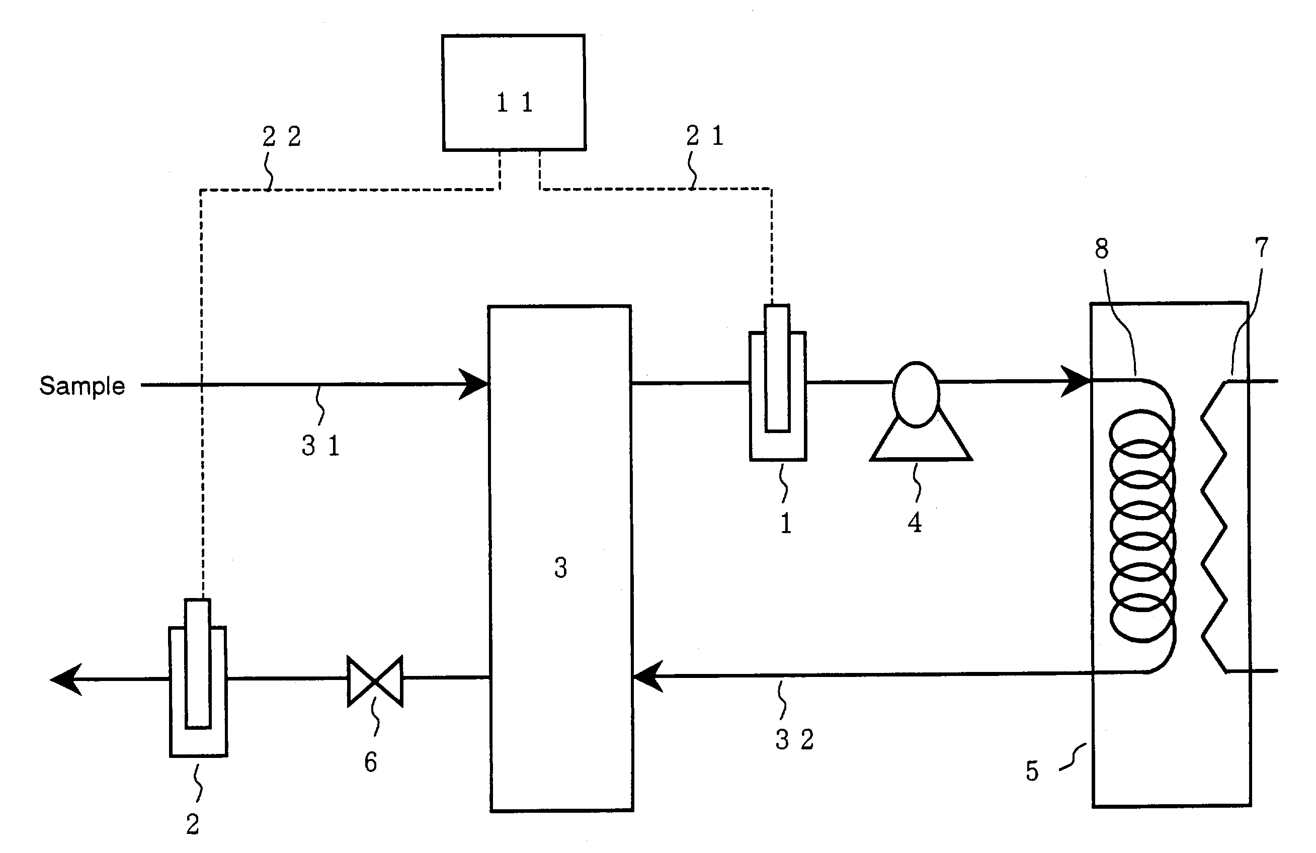
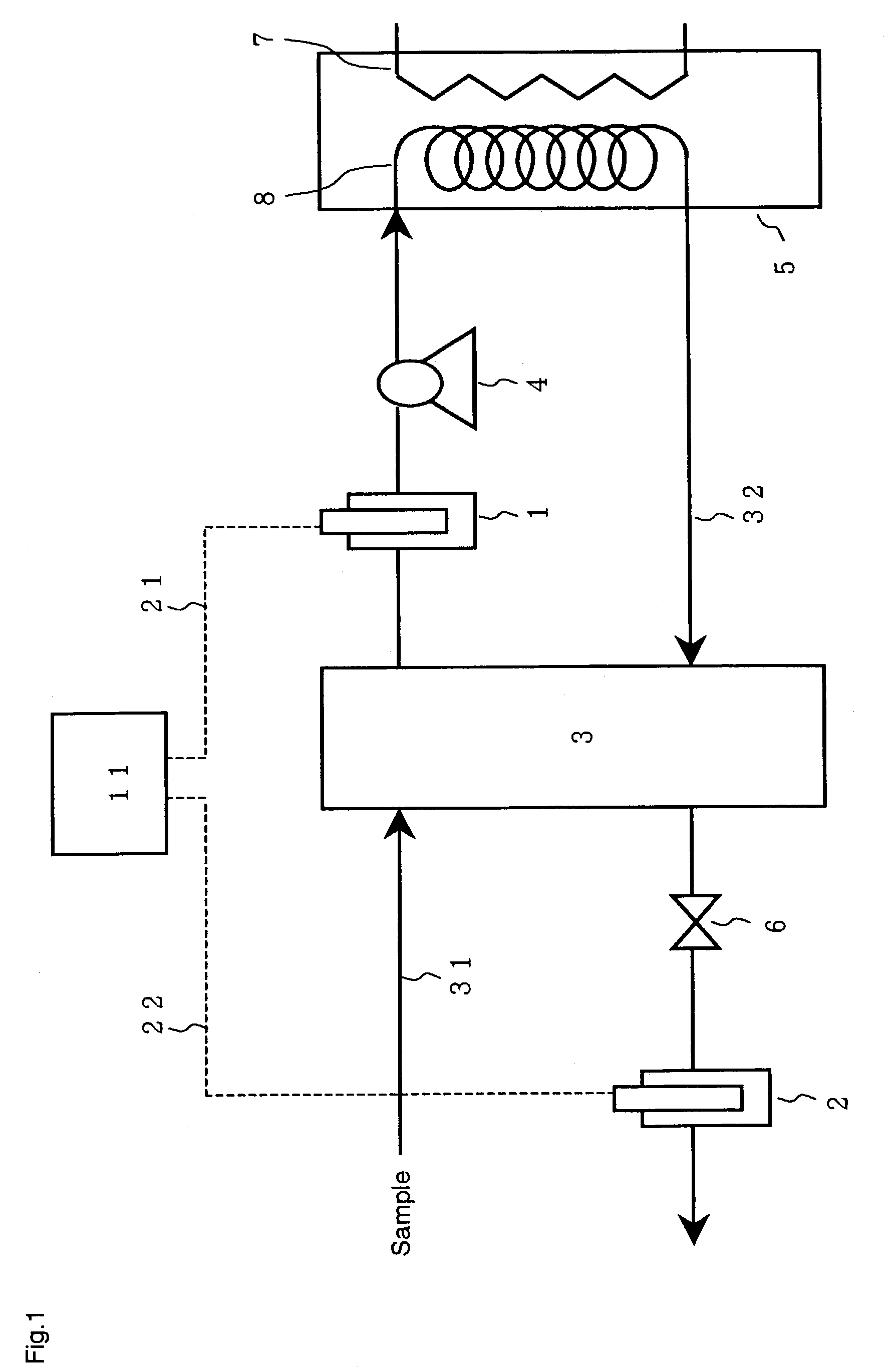
[0065]In the apparatus shown in FIG. 1, the sensors 1 and 2 were conductivity meters from HORIBA Inc. (Model: TD-920). The cooling means 3 was a cooler using water. The pressurizing means 4 was a metering pump from Nippon Seimitsu Kagaku Inc. (Model: NR-S-702). The heating means in the reactor 5 was an electric heater, and a coiled stainless tube was placed in the reactor as the reaction vessel 8. All the pipes in the apparatus were made of stainless steel. The pressure-retaining means 6 was a commercially available pressure regulator that may be used for an ammonia-containing solution.

[0066]In this apparatus, a part of a solution containing ammonia and urea from a condensate facility in a urea production process was fed through a line 31 into the cooler at a rate of 10 mL / min. The sample solution was cooled to 25° C. and electric conductivity χ′ was then determined by the sensor 1. The solution was subsequently introduced into the reactor while being pressurized to 2.5 MPaG by the ...

reference example 1

[0071]Electric conductivity χ′ was determined by the sensor 1 as described in Example 1 for an ammonia-containing aqueous solution that contained no substances, other than ammonia, that may influence electric conductivity. As a result, the ammonia concentration was determined to be 10 ppm. For confirmation, the above solution was measured for its ammonia concentration by the indophenol method. These measurement results are shown in Table 2. As seen from Table 2, for an ammonia concentration, there is also good conformity between the measurement results according to this invention and those for confirmation.

example 2

[0072]Measurement was conducted for an aqueous solution containing urea in which substances influencing an electric conductivity other than urea are negligible under the apparatus / measurement conditions described in Example 1. As a result, urea concentration was determined to be 10 ppm. For confirmation, the above solution was measured for its urea concentration by PDBA colorimetry. These measurement results are shown in Table 2. As seen from Table 2, there is good conformity between the measurement results according to this invention and those for confirmation, indicating that the measuring method and the apparatus according to this invention are effective.


PUM

PropertyMeasurementUnit
temperatureaaaaaaaaaa
electric conductivityaaaaaaaaaa

Abstract

A method for determining a urea concentration in an aqueous solution containing urea, includes: hydrolyzing the urea in the aqueous solution, measuring an electric conductivity χ of the aqueous solution, and determining the urea concentration in the aqueous solution from the electric conductivity χ using a correlation between the urea concentration and an electric conductivity.

Description

BACKGROUND OF THE INVENTION[0001]1. Field of the Invention[0002]This invention relates to a method for determining a urea concentration in an aqueous solution and an apparatus therefor. This invention may be suitably applied to, for example, a method and an apparatus for determining a urea concentration in a condensate processed in a condensate processing facility during a urea production process, and an apparatus that is capable of sending a signal for controlling a destination of the condensate, based on a urea concentration to a controller such as a distributed control system (DCS).[0003]2. Description of the Related Art[0004]In the past, techniques such as colorimetry or application of a nitrogen analyzer have been used to determine a concentration of urea in a solution. After removing dissolved urea, ammonia and carbon dioxide from the condensed water, the condensed water is then recycled to the production process for being reused as water required in the production process. Th...

Claims


Application Information

Patent Timeline
Patent Type & Authority Patents(United States)
IPC IPC(8): G01N33/00G01N27/08G01N27/10G01N27/02G01N27/06G01N31/00
CPCG01N27/021G01N31/002Y10T436/171538Y10T436/117497Y10T436/175383
Inventor TAJIRI, YOSHIHIROHAYABUCHI, TAKUYATERAMOTO, NAOHIROKOJIMA, YASUHIKOSAKATA, EIJIMORIKAWA, HARUYUKI
Owner TOYO ENG CORP
Why Eureka
Try Eureka