
Differential amplifier, data driver and display device

a technology of data driver and amplifier, applied in the direction of logic circuit coupling/interface arrangement, pulse technique, instruments, etc., can solve the problems of increasing current consumption, increasing power dissipation, and loss of stability, so as to achieve high speed operation, the useful life of the battery is not crucial, and the data line load capacitance is increased.

Active Publication Date: 2006-12-26
RENESAS ELECTRONICS CORP
View PDF6 Cites 34 Cited by
  • Summary
  • Abstract
  • Description
  • Claims
  • Application Information

AI Technical Summary

Benefits of technology

The solution enables high-speed operation with reduced power dissipation, even during frequent charging and discharging cycles, by utilizing bootstrap action and phase compensation, thus addressing the limitations of conventional amplifiers in handling increased load capacitance and high-definition display requirements.

Problems solved by technology

However, the conventional differential amplifier suffers from a drawback that, if the high operating speed is to be realized as the stable operation is maintained, the power dissipation is increased.
Thus, there persists a problem that, even though the current flowing through the differential pair needs to be increased or the phase compensation capacity needs to be decreased to improve the slew rate, the current consumption is increased if the current through the differential pair is increased, while stability is lost if the phase compensation capacity is decreased.

Method used


Image

  • Differential amplifier, data driver and display device
  • Differential amplifier, data driver and display device
  • Differential amplifier, data driver and display device

Examples


embodiment

[Embodiment]

[0122]For more detailed explanation of the above-described embodiments, preferred embodiments of the present invention are now explained with reference to the drawings, in which the devices of the same structure or functional blocks performing the same functions are depicted by the same reference numerals. In the respective drawings, the transistors are insulated gate transistors, unless otherwise specified.

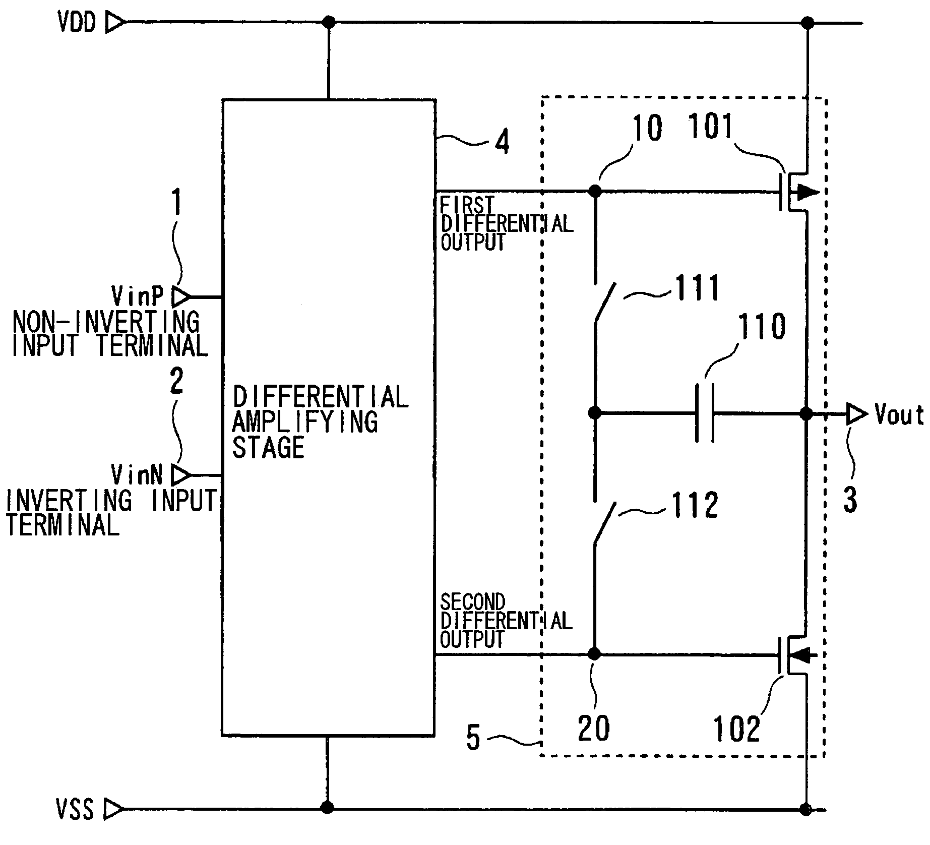
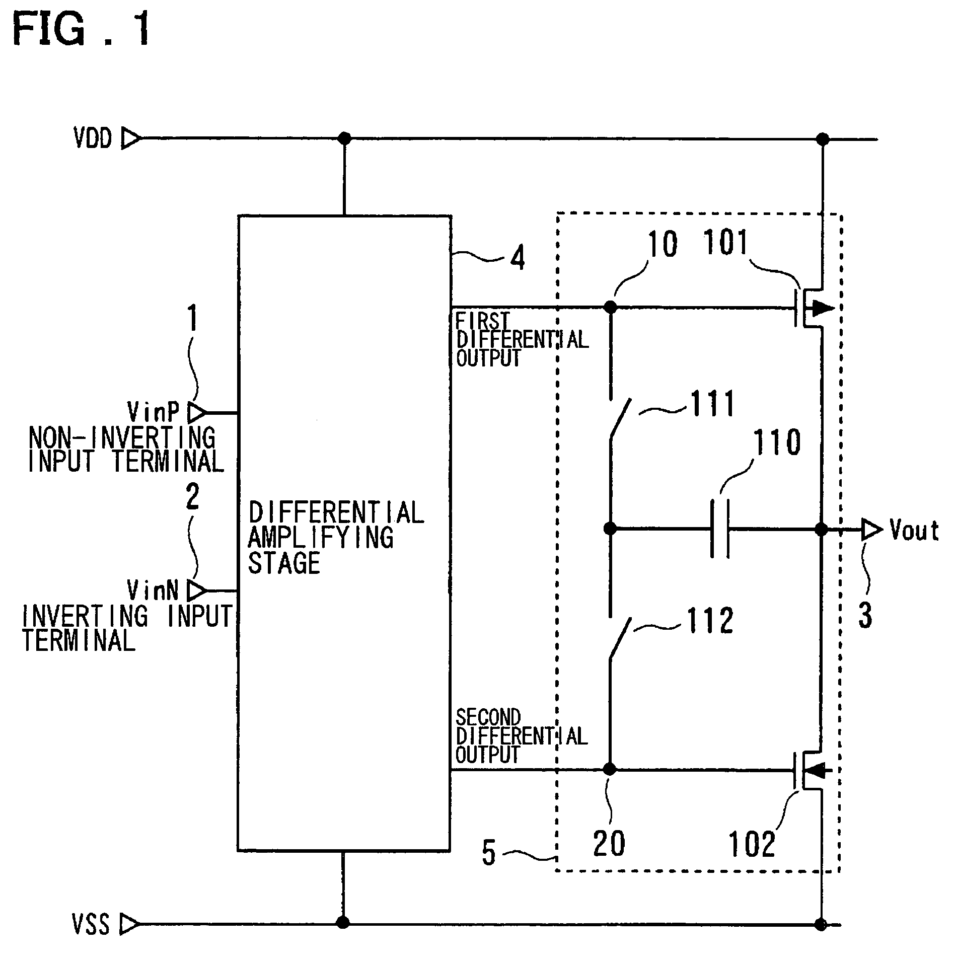
[0123]Referring to FIG. 1, a differential amplifier of a first embodiment of the present invention, is made up by a differential amplifying stage 4, including a non-inverting input terminal 1, an inverting input terminal 2, a first differential output terminal 10 and a second differential output terminal 20, and by an output amplifying stage (output driving stage) 5, including a P-channel transistor 101, connected across an output terminal 3 and a high potential side power supply VDD, and having a gate connected to the first differential output terminal 10, an N-chann...


PUM


Abstract

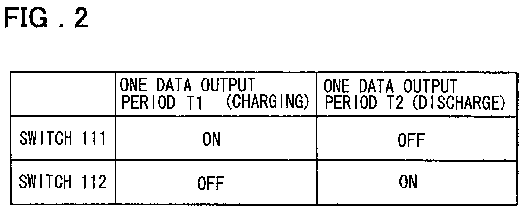
A differential amplifier includes a differential amplifying stage and an output amplifying stage. The output amplifying stage includes a first transistor for pull-up, a second transistor for pull-down, a capacitor element, and switches. The first transistor for pull-up is connected across an output terminal and a high potential side power supply VDD and has a control terminal to which is connected a first differential output. The second transistor for pull-down is connected across the output terminal and a low potential side power supply VSS and has a control terminal to which is connected a second differential output. The switches interchangeably connect the capacitor element across the output terminal and the control terminal of the first transistor for pull-up or across the output terminal and the control terminal of the second transistor for pull-down.

Description

FIELD OF THE INVENTION[0001]This invention relates to a differential amplifier and a display device employing the same.BACKGROUND OF THE INVENTION[0002]Recently, as a display device, a liquid crystal display device (LCD), featured by a thin thickness, a light weight and low power dissipation, has come into extensive use, and is widely used for a display unit of mobile equipment, such as mobile phone, PDA (personal digital assistant) or a notebook PC (personal computer). However, the technique for enlarging the display size of the display device or coping with a moving picture has made progress, such that a stationary large-size display device or a large display size liquid crystal television receiver has now been offered to the market. As the liquid crystal display device, a liquid crystal display device of an active matrix driving system, capable of high definition display, is currently used.[0003]FIG. 28 illustrates a liquid crystal display device. It is noted that FIG. 28 shows o...

Claims


Application Information

Patent Timeline
Patent Type & Authority Patents(United States)
IPC IPC(8): H03F3/45G09G3/20G09G3/36H03F1/02H03F3/30H03K17/04H03K17/16H03K17/687H03K19/017H03K19/0175H03K19/0948
CPCH03F3/3022H03F3/303H03F3/4521H03F3/45475H03F2203/45726
Inventor TSUCHI, HIROSHI
Owner RENESAS ELECTRONICS CORP
Learn More