Microsurgical robot system

a robot system and micro-scopy technology, applied in the field of micro-scopy robot systems, can solve the problems of limited surgical precision, difficult to achieve precise localization of brain pathology and neural structures, and surgeons currently have no effective way to use imri data to enhance surgical precision and dexterity, so as to facilitate safety and tool changing, the effect of reducing patient risk

Active Publication Date: 2006-12-26
DEERFIELD IMAGING INC
View PDF9 Cites 1541 Cited by
  • Summary
  • Abstract
  • Description
  • Claims
  • Application Information

AI Technical Summary

Benefits of technology

[0073]Clinical curbs also minimize patient risk. The current robot is excluded from performing skull exposure, as this would be a relatively difficult task for a robot but is efficiently accomplished by a surgeon. Similarly, burr-holes and bone-flaps are executed by surgeons.
[0074]The system provides an MR-compatible ambidextrous robotic system capable of microsurgery and stereotaxy. With additional surgical toolsets this system lends itself to other discipl

Problems solved by technology

They also have physiological limits to their precision, tactile sensibility and stamina.
Furthermore, the precise localization of brain pathology and neural structures is often difficult to achieve during surgery due to brain shifts and deformations as the operation progresses.
While Intra-operative Magnetic Resonance Imaging (iMRI) has been used to monitor brain deformations, the surgeon currently has no effective way to use the iMRI data to enhance the precision and dexterity of surgery.
They are compelled to rely on old techniques, and do not take advantage of these exquisite, updated images.
Consequently, the quality of the surgery and outcomes is variable, and too often sub-optimal.
Unfortunately, there are no surgical robots that provide the surgeon with an ambidextrous and precise surgical system that uses updated iMRI patient data to achieve accurate image-guided surgery.
In addition, there is no surgical robot with force sensing technology that is compatible with MRI systems.
MIS robots are not su

Method used


Image

  • Microsurgical robot system
  • Microsurgical robot system
  • Microsurgical robot system

Examples


Embodiment Construction

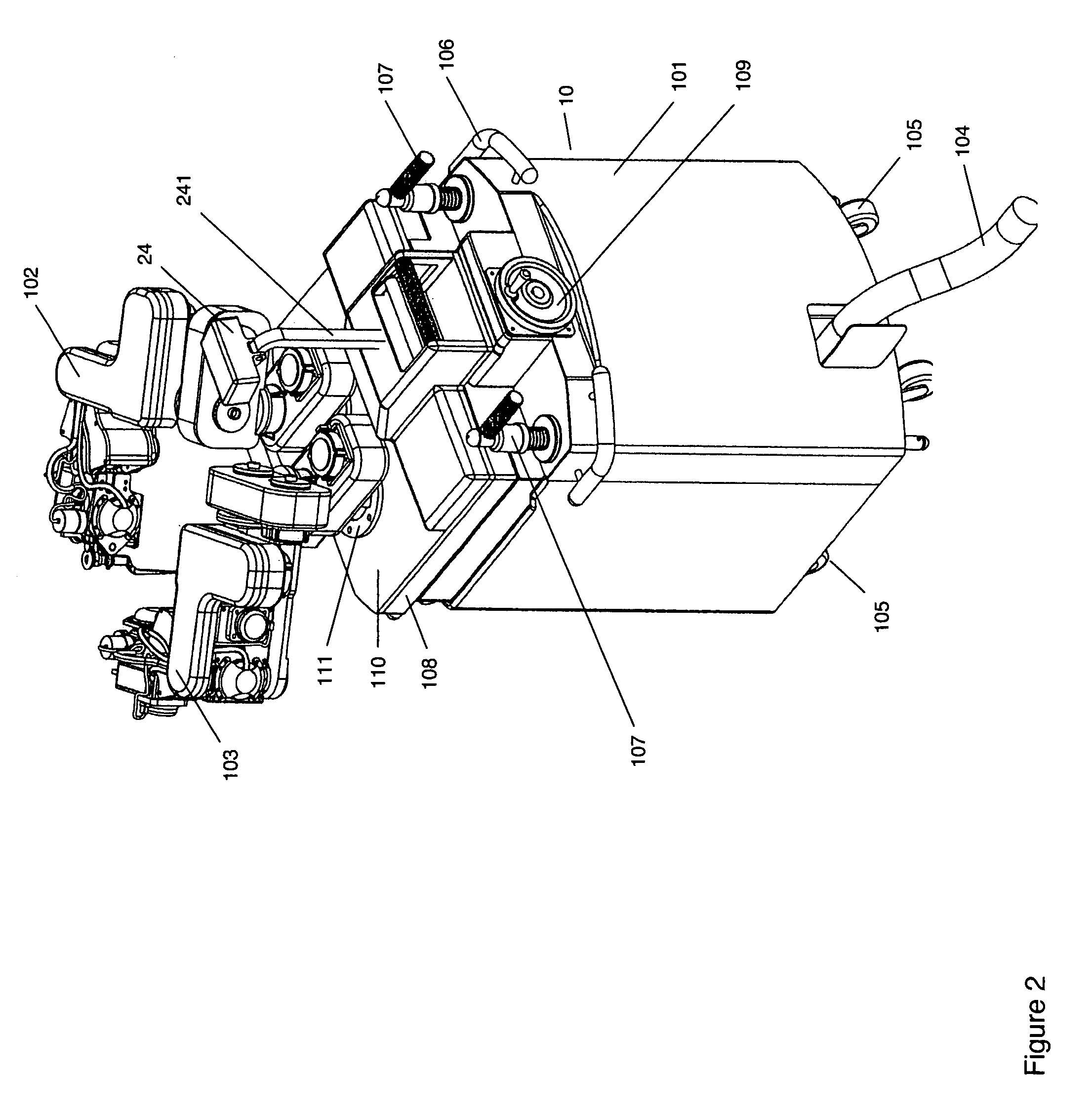
[0092]Further details of the above generally described system are shown in the attached drawings 1 through 17.

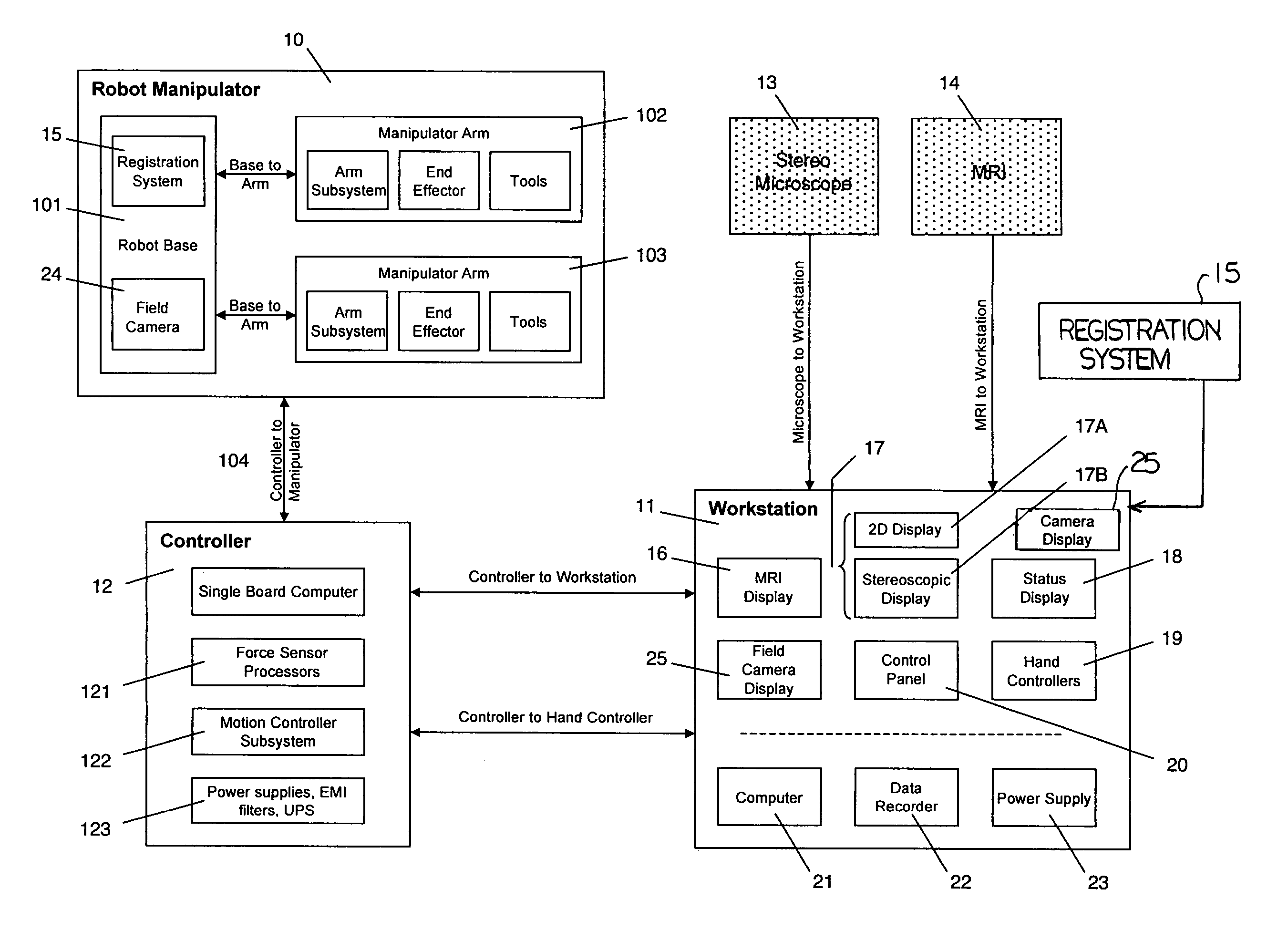
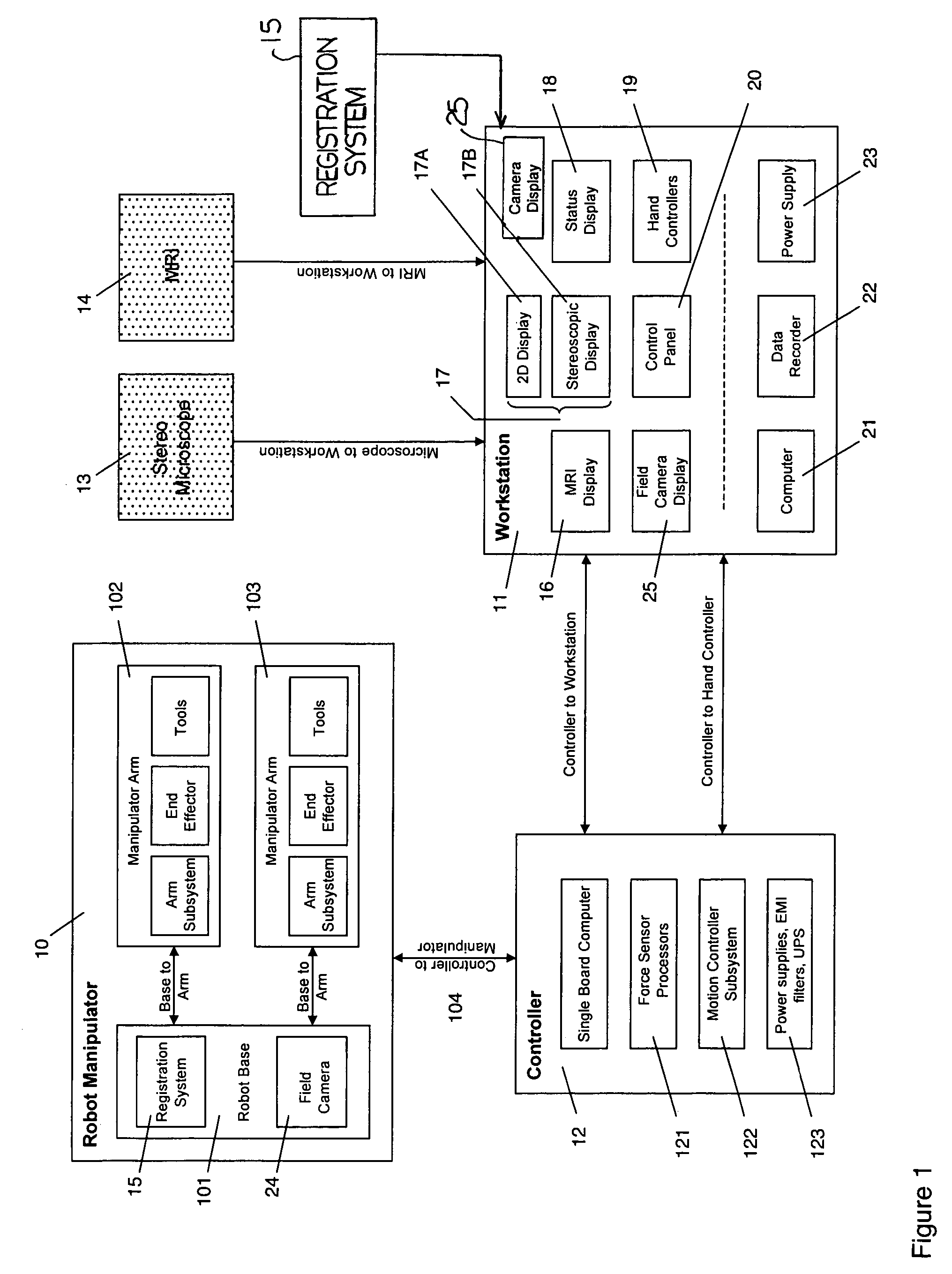
[0093]An overview of the system is shown in FIG. 1 which comprises a robot manipulator 10, a work station 11 and a controller 12 which communicates between the robot manipulator and the work station. As inputs to the work station is also provided a stereo microscope 13, an MRI imaging system 14 and a registration system 15.

[0094]The work station includes a number of displays including at first display 16 for the MRI image, a second display 17 for the microscope image and a third display 18 for the system status. Further the work station includes two hand controllers schematically indicated at 19 and an input interface 20 allowing the surgeon to control the systems from the work station while reviewing the displays. The work station further includes a computer or processor 21, a data recording system 22 and a power supply 23.

[0095]The display 17 includes a stereoscopic displa...


PUM


Abstract

A robot system for use in surgical procedures has two movable arms each carried on a wheeled base with each arm having a six of degrees of freedom of movement and an end effector which can be rolled about its axis and an actuator which can slide along the axis for operating different tools adapted to be supported by the effector. Each end effector including optical force sensors for detecting forces applied to the tool by engagement with the part of the patient. A microscope is located at a position for viewing the part of the patient. The position of the tool tip can be digitized relative to fiducial markers visible in an MRI experiment. The workstation and control system has a pair of hand-controllers simultaneously manipulated by an operator to control movement of a respective one or both of the arms. The image from the microscope is displayed on a monitor in 2D and stereoscopically on a microscope viewer. A second MRI display shows an image of the part of the patient the real-time location of the tool. The robot is MRI compatible and can be configured to operate within a closed magnet bore. The arms are driven about vertical and horizontal axes by piezoelectric motors.

Description

[0001]This application claims priority under 35 U.S.C. 119 from U.S. Provisional Application Ser. No. 60 / 402,724 filed Aug. 13, 2002.BACKGROUND OF THE INVENTION[0002]Complication avoidance in microsurgery (neurosurgery, ophthalmology, otorhinolaryngology, limb and digit reattachment) is crucial, and minimizes patient morbidity and health care costs. Current operative techniques rely on human surgeons, who have variable skill and dexterity. They also have physiological limits to their precision, tactile sensibility and stamina. Furthermore, the precise localization of brain pathology and neural structures is often difficult to achieve during surgery due to brain shifts and deformations as the operation progresses. While Intra-operative Magnetic Resonance Imaging (iMRI) has been used to monitor brain deformations, the surgeon currently has no effective way to use the iMRI data to enhance the precision and dexterity of surgery. They are compelled to rely on old techniques, and do not t...

Claims


Application Information

Patent Timeline
IPC IPC(8): G06F19/00A61B19/00
CPCA61B19/22A61B19/2203A61B19/5212A61B19/5223A61B19/5244A61B19/54A61B19/56A61B2017/00911A61B2019/2223A61B2019/223A61B2019/2234A61B2019/2242A61B2019/2269A61B2019/2288A61B2019/2292A61B2019/2296A61B2019/464A61B2019/502A61B2019/5236A61B2019/5259A61B2019/5287A61B34/20A61B34/25A61B34/30A61B34/35A61B34/37A61B34/70A61B34/71A61B34/74A61B34/75A61B34/76A61B34/77A61B90/20A61B90/25A61B90/361A61B90/39A61B2034/102A61B2034/2059A61B2034/305A61B2090/064A61B2090/363A61B2090/374
Inventor SUTHERLAND, GARNETTE ROYLOUW, DEON FRANCOISMCBETH, PAUL BRADLEYFIELDING, TIMGREGORIS, DENNIS JOHN
Owner DEERFIELD IMAGING INC
Why Eureka
Try Eureka