Transmission/reception integrated radio-frequency apparatus

a radio-frequency apparatus and integrated technology, applied in the field of transmission/reception integrated radio-frequency apparatuses, can solve the problems of interference with weak downstream signal, inability to receive correct signal from center station, and loss of semiconductor devices in cable modems, so as to prevent noise interference, prevent transmission of noise, and high communication quality and reliability

Inactive Publication Date: 2007-01-02
KK TOSHIBA
View PDF45 Cites 39 Cited by
  • Summary
  • Abstract
  • Description
  • Claims
  • Application Information

AI Technical Summary

Benefits of technology

[0018]Another object of the invention is to provide a transmission / reception integrated RF apparatus which can prevent a harmonic component produced, from an overvoltage protection circuit, from adversely affecting a downstream signal.
[0019]Still another object of the invention is to provide a transmission / reception integrated RF apparatus which can prevent transmission of noise to a general line, even if an upstream signal transmission circuit abnormally operates and continues transmission over an assigned time zone, and can prevent noise from interfering with upstream and downstream signals for other users.
[0020]Still another object of the invention is to provide a transmission / reception integrated RF apparatus which can surely maintain isolation between a radio-frequency processing section and a connection line, even if a circuit for generating an upstream signal and a circuit for processing an intermediate-frequency signal are integrated in an LSI, and can maintain high communication quality and reliability.
[0021]Still another object of the invention is to provide a transmission / reception integrated RF apparatus which can prevent occurrence of ripple in the power supply voltage of a local oscillator for frequency-converting a downstream signal, even if an upstream signal transmission circuit is switched between an active state and an inactive state, and can maintain high reception quality of the downstream signal.

Problems solved by technology

If overvoltage is applied due to indirect lightning stroke, semiconductor devices in the cable modem may be destroyed.
If the upstream transmission circuit continues to send noise at a time zone other than the assigned one, the noise will be superimposed on the other user's upstream signal to which this time zone is assigned, and the center station cannot receive a correct signal.
(1) Since the level of the upstream signal is high, a harmonic component produced by the overvoltage protection circuit may interfere with the weak downstream signal. For example, when an upstream signal of 40 MHz is being transmitted, a third harmonic (120 MHz) of 40 MHz may interfere with a downstream signal of 120 MHz.
(2) If a certain user's cable modem continues to be in the active state over the assigned transmission time zone, noise may be sent to the cable and the center station may fail to exactly receive an upstream signal from some other user's cable modem.
(3) Where a circuit for transmitting an upstream signal (transmission signal) and a circuit for processing a downstream intermediate-frequency signal are integrated in an LSI for the purpose of reduction in size of circuit components, the upstream transmission signal may interfere with the downstream intermediate-frequency signal on a connection line between each circuit and an RF processing section.
(4) The upstream signal transmission circuit is activated / deactivated between the transmission time zone and the non-transmission time zone. With the activation / deactivation, a circuit current in the upstream signal transmission circuit may vary and a ripple may occur in the power supply voltage of a local oscillator which frequency-converts the downstream signal. If a ripple occurs in the power supply voltage of the local oscillator, side-band spuriousness may be caused and the quality of reception of the downstream signal may deteriorate.

Method used


Image

  • Transmission/reception integrated radio-frequency apparatus
  • Transmission/reception integrated radio-frequency apparatus
  • Transmission/reception integrated radio-frequency apparatus

Examples


Embodiment Construction

[0047]An embodiment of the present invention will now be described with reference to the accompanying drawings.

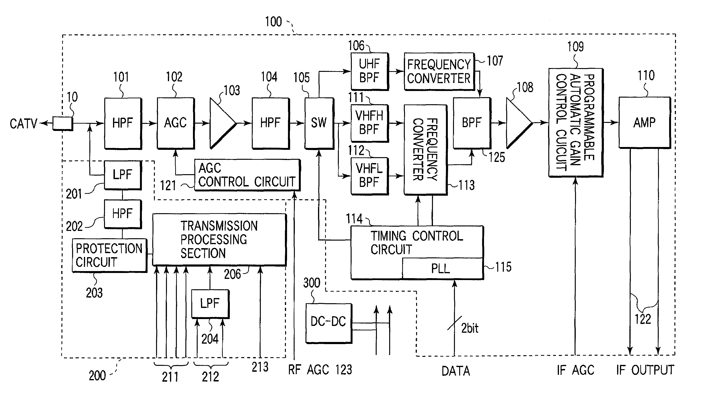
[0048]FIG. 1 shows a whole structure of a radio-frequency (RF) apparatus to which the present invention is applied. A block indicated by a broken line 100 denotes a reception system block, and a block indicated by a broken line 200 denotes a transmission system block. A coaxial cable of a CATV network is connected to an input / output (I / O) terminal 10. The I / O terminal 10 is connected to a high-pass filter 101. The I / O terminal 10 is also connected to a low-pass filter 201 (to be described later). A downstream signal (RF reception signal) input to the I / O terminal 10 is delivered to an automatic gain control (AGC) circuit 102 via the high-pass filter 101. The gain-controlled input is then delivered to a switch 105 via an amplifier 103 and a high-pass filter 104.

[0049]An output terminal of the switch 105 is connected to a UHF band-pass filter 106 for UHF, a high VHF band-pass...


PUM


Abstract

There is provided a highly reliable transmission / reception integrated radio-frequency apparatus which can achieve a high communication quality in a cable modem. A reception RF signal is input to a reception system block via an input / output terminal, converted to an intermediate-frequency signal, and output from a terminal. An output terminal of a transmission processing section of a transmission system block is connected to the input / output terminal via an overvoltage protection circuit, a high-pass filter functioning as a countermeasure to overvoltage, and a low-pass filter for suppressing harmonics produced from the high-pass filter.

Description

CROSS-REFERENCE TO RELATED APPLICATIONS[0001]This application is based upon and claims the benefit of priority from the prior Japanese Patent Application No. 2000-198475, filed Jun. 30, 2000, the entire contents of which are incorporated herein by reference.BACKGROUND OF THE INVENTION[0002]The present invention relates to a transmission / reception integrated radio-frequency (RF) apparatus used on a terminal side connected to, e.g. a two-way cable television (CATV) network.[0003]With recent development in multi-media technology and digital technology in the fields of broadcasting and communications, amalgamation of broadcasting and communications technologies will shortly be realized. For example, a CATV line, which has a higher data transmission capacity than a telephone line, may be utilized to constitute a network, over which data communication services can be provided. In this case, a communication device (e.g. a personal computer), serving as a subscriber terminal, is connected t...

Claims


Application Information

Patent Timeline
Patent Type & Authority Patents(United States)
IPC IPC(8): H04N7/173H04B1/04H04N7/16H04L5/16H02H7/20H02H9/04H04B1/18H04B1/40H04B3/02H04N7/10H04N21/61H04N21/647
CPCH04B1/40H04N7/102
Inventor ABE, SHUJIKUDO, KATSUYAOOSAWA, MASAMI
Owner KK TOSHIBA
Why Eureka
Try Eureka