
System and method for gettering gas-phase contaminants within a sealed enclosure

a technology of sealed enclosure and gas-phase contaminants, which is applied in the direction of dispersed particle separation, chemistry apparatus and processes, separation processes, etc., can solve the problems of reliability, damage, and reduction of device life, and the atmosphere dew point to exceed,

Inactive Publication Date: 2007-01-09
EM4
View PDF13 Cites 30 Cited by
  • Summary
  • Abstract
  • Description
  • Claims
  • Application Information

AI Technical Summary

Benefits of technology

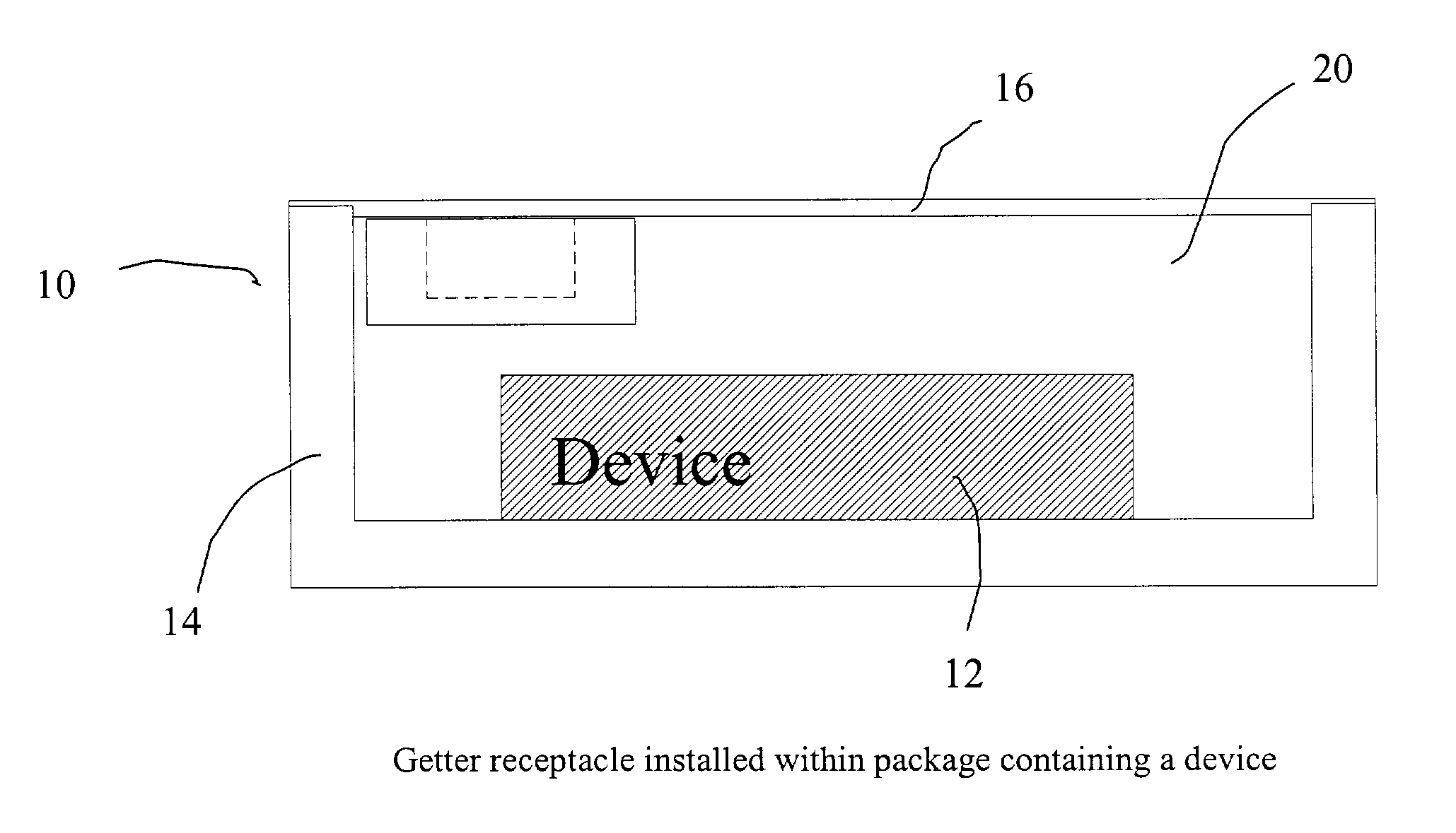
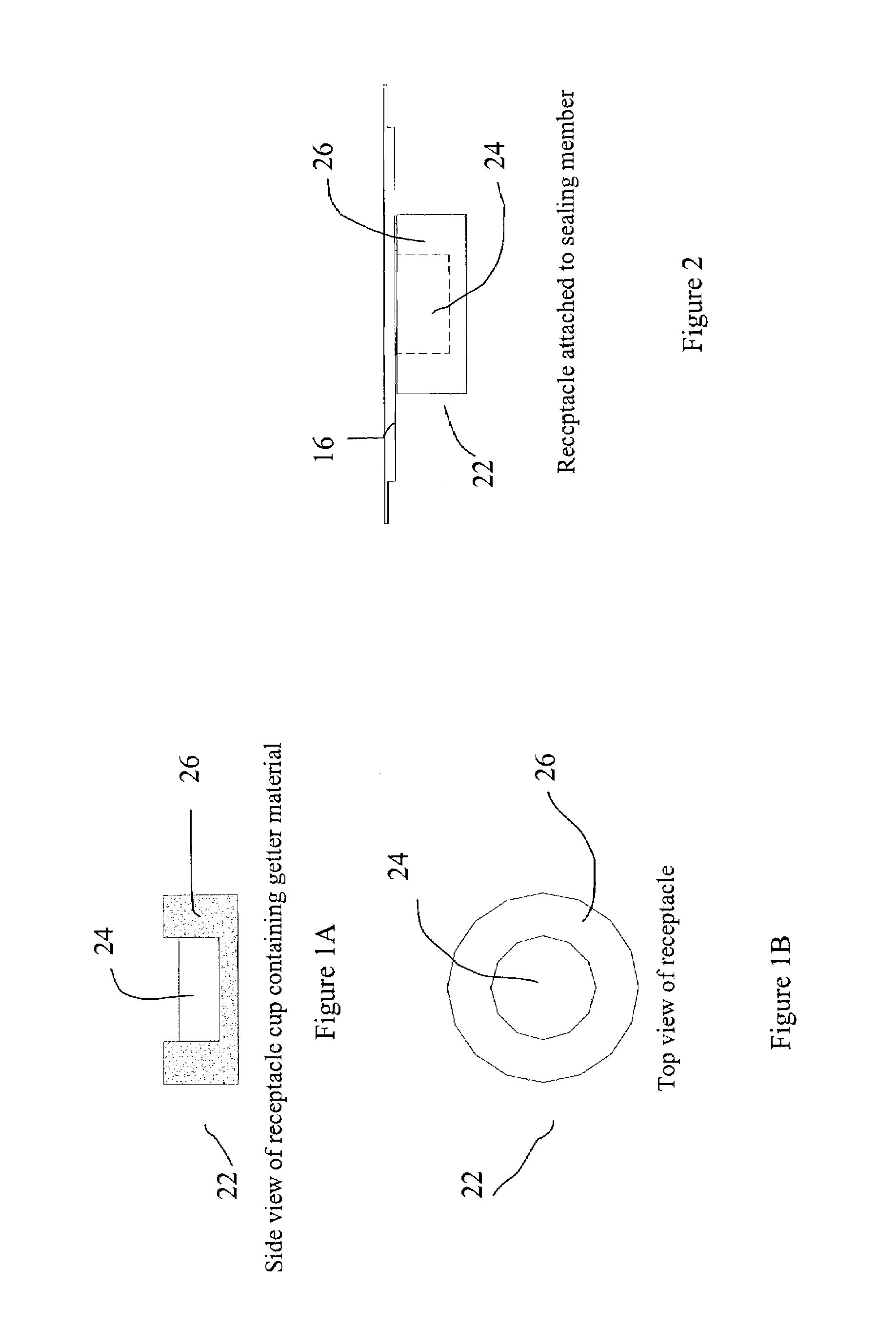
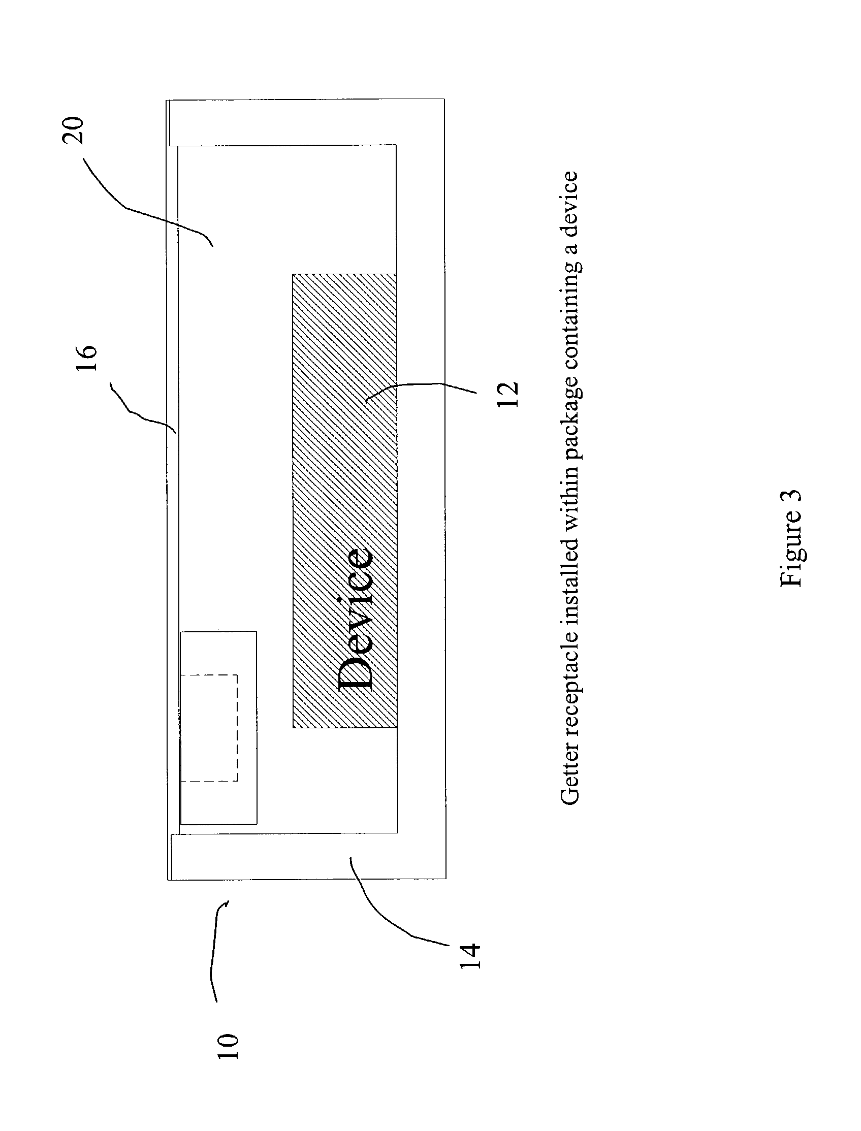
[0015]In an alternative embodiment according to the present invention, a method is provided for protecting a device in a sealed enclosure from contaminants that diffuse or leak into the enclosure. The enclosure is divided into a getter subvolume and a device subvolume with a partition that is permeable to gas-phase molecules but not to solid particles. The device is housed in the device subvolume. Contaminant molecules that permeate through the partition into the getter subvolume are immobilized with a getter material. The getter material is a powdered and / or granular solid with a particle size that precludes passage of the getter material through the partition into the device subvolume. Both the original getter material and its reaction products are stable in that they do not provide any potential contamination issues themselves.

Problems solved by technology

Another industry in which it can be important to remove impurities is in packaging of hermetically sealed electronic devices in which moisture, other gases, and / or particulates may cause issues with reliability, damage, and reduction of device lifetime.
Given sufficient time, the amount of water vapor generated through either or both mechanisms can cause the internal atmosphere dew point to exceed the operational or storage temperature, whereupon the water vapor condenses to liquid form.
Reduction of solid oxides may lead to an impairment of the device performance by altering the electrical or optical characteristics.
Condensation of water can lead to contamination, corrosion, and other types of chemical and / or physical damage.
Many microelectronic and optoelectronic devices are sensitive to moisture with consequent effects on reliability due to corrosion or other alteration of contact materials.
Heating and cooling may compound the problem.
Formations such as dendritic growth and metal whiskers can occur, with detrimental effects on device functioning.
Corrosion occurs when a contaminant behaves as a catalyst with water to oxidize metallization and continues until all of the available water is consumed, generally resulting in device failure.
In addition to the aforementioned problems that may be caused by water formation from reactions of oxygen with hydrogen, enclosures that include ferrous alloys and other metallic materials such as, for example, gallium arsenide are particularly sensitive to damage due to hydride formation.
Metal hydrides are gradually oxidized, which may result in device failures in both silicon and gallium arsenide devices.
The potential for device damage is also of concern for optoelectronic technologies.
Coatings or films on optical surfaces may be negatively affected or degraded as well.
In addition, a perfect hermetic seal is not practically achievable.
Although this system is capable of operating at low temperature, it has several potential weaknesses.
This substantially diminishes the protective effect.
However this temperature-reversible effect is undesirable in general.
All of these prior art getters suffer from the introduction of organic materials, such as would be used for the binder, into the sealed cavity.
Organic compounds are a particular concern in the packaging of optoelectronic devices, due to contamination of the optical surfaces and consequential impairment to operation.

Method used


Image

  • System and method for gettering gas-phase contaminants within a sealed enclosure
  • System and method for gettering gas-phase contaminants within a sealed enclosure
  • System and method for gettering gas-phase contaminants within a sealed enclosure

Examples


experimental examples

Theoretical and Experimental Examples

[0041]The gettering capacity required for a given package or other enclosure into which gas-phase contaminants may diffuse or leak may be estimated based on the outgassing properties of the components and devices being housed within the package in addition to an estimate of the quantity of evolved H2O from the H2 outgassing from the package material. Table I shows the calculated capacity required for a getter assembly used in various packages. It can be seen that the reduction in package volume requires that the proportion of that volume taken up by the getter assembly increases due to the effective increase in ppmv of hydrogen (H2) desorbed by the package walls for a ferrous material. Even if that ferrous package is replaced by some other non-hydrogen desorbing material one or more other factors may account for potential sources of contaminant, such as, for example, an increased leak-rate at the package seal. Clearly, this may be an issue for pl...


PUM

PropertyMeasurementUnit
pore sizeaaaaaaaaaa
temperaturesaaaaaaaaaa
temperatureaaaaaaaaaa

Abstract

A getter and method for making is provided for removing unwanted impurities from the main body of a sealed hermetic enclosure or package containing one or more devices or objects that have sensitivity to contact with the impurity. The getter may be formulated from granular or powdered materials that react with gas-phase impurities through a combination of chemisorption and absorption mechanisms to form one or more stable species. A porous receptacle is included that contains the getter material such that it cannot penetrate into the main body of the sealed package while allowing the gases in the main body of the package, including the target impurities, to pass freely into the receptacle where they are subsequently rendered immobile by the action of the getter material.

Description

RELATED APPLICATIONS[0001]This application claims priority to U.S. Provisional Patent Application Ser. No. 60 / 395,286, filed on Jul. 12, 2002, the disclosure of which is hereby rated by reference in its entirety.FIELD OF THE INVENTION[0002]This invention relates generally to the control of gas-phase or other airborne impurities or contaminants, and more specifically to methods and apparatus for removing gas-phase impurities or contaminants from the atmosphere of a sealed device enclosure such as for instance, a packaged device, in particular, an optoelectronic device that has sensitivity to moisture and hydrogen. Inclusion of a material with a mechanism to immobilize the impurity lessens failure and performance reduction issues associated with reactions of impurities and / or contaminants with the device. This material is enclosed separately from the device so that it may be exposed to the airborne impurities or contaminants without coming into contact or otherwise contaminating the d...

Claims


Application Information

Patent Timeline
Patent Type & Authority Patents(United States)
IPC IPC(8): H01L29/76
CPCB01J20/041B01J20/06B01J20/2805H01L23/26B01J2220/42H01L2924/0002H01L2924/09701H01L2924/1423H01L2924/00
Inventor WAKELIN, SUZANNE
Owner EM4
Learn More