Multi-port cross-connected multi-level cascode differential amplifier

a differential amplifier and multi-port technology, applied in the field of amplifiers, can solve the problems of increasing the performance constraints of the ic, the low output signal amplitude per amplifier stage, and the limitations of the cascode circuitry, including the limitations of bandwidth, and the allowable signal swing, so as to increase the current gain, input impedance, and amplifier bandwidth.

Inactive Publication Date: 2007-01-09
IBM CORP
View PDF7 Cites 23 Cited by
  • Summary
  • Abstract
  • Description
  • Claims
  • Application Information

AI Technical Summary

Benefits of technology

[0014]Some preferred embodiments of the present invention provide a differential amplifier using cascode circuitry in two branches of the amplifier. The common emitter / source and common base / gate inputs of the two branches are cross-connected, the cross-connections increasing the current gain, the input impedance, and the bandwidth of the amplifier.
[0016]In disclosed embodiments of the present invention, the differential amplifier comprises two cascode circuits, each cascode circuit in turn comprising an input transistor connected in series to an output transistor. The base / gate of each cascode circuit's input transistor is cross-connected to the base / gate of the output transistor of the other cascode circuit, with appropriate DC adjustment. The two cross-connections provide a simple and effective way to decrease the required input current in each cascode circuit. The decreased input current in turn increases the amplifier current gain and also its input impedance. The bandwidth of the amplifier also increases compared to conventional cascode amplifiers.

Problems solved by technology

As transistors in an integrated circuit (IC) are reduced in size, further limitations such as reduced maximum allowable voltage drop place increased constraints on the performance of the IC.
For an IC operating as an amplifier, the constraints, especially for high frequency amplifiers, lead to low output signal amplitude per amplifier stage.
Notwithstanding the circuits of the prior art described above, limitations of cascode circuitry, including limitations on the current gain, the input impedance, the bandwidth, and the allowable signal swing, still exist.

Method used


Image

  • Multi-port cross-connected multi-level cascode differential amplifier
  • Multi-port cross-connected multi-level cascode differential amplifier
  • Multi-port cross-connected multi-level cascode differential amplifier

Examples


Embodiment Construction

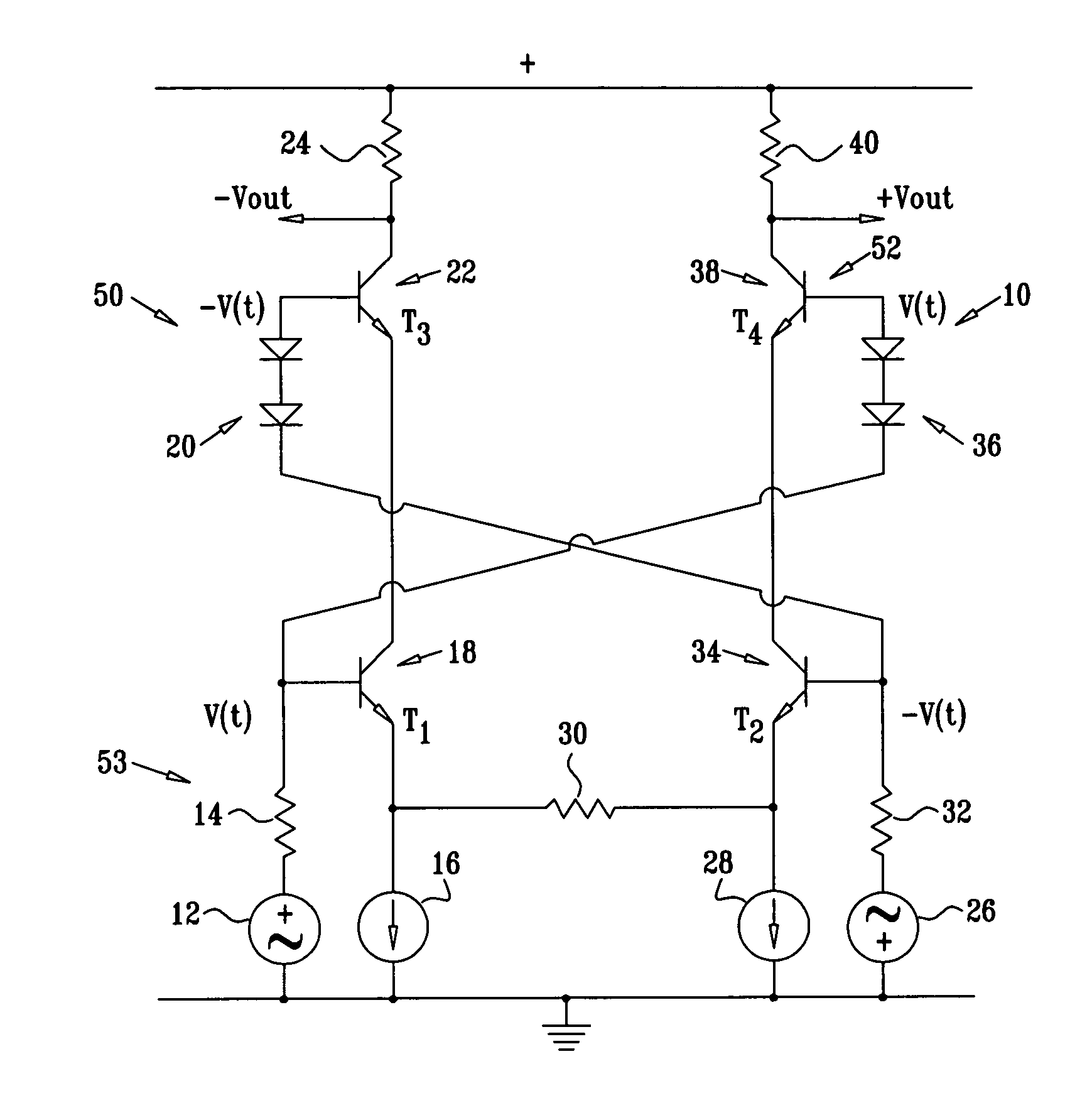
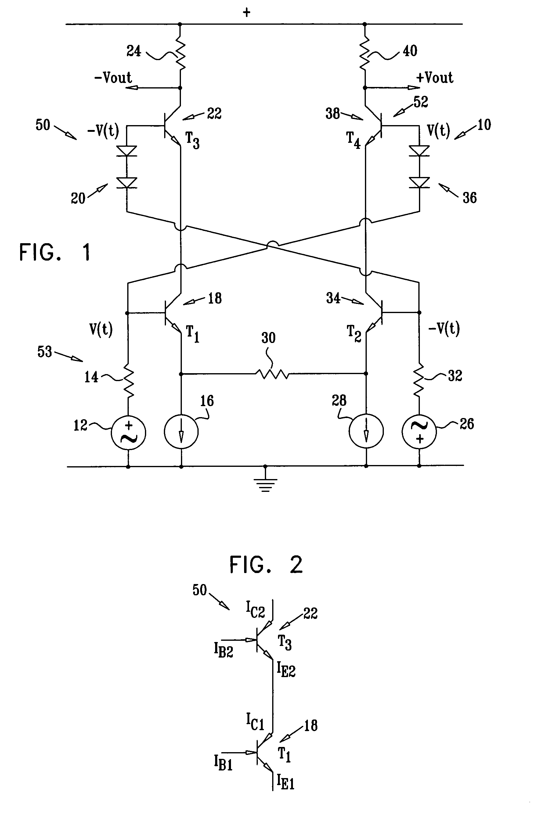
[0142]Reference is now made to FIG. 1, which is a schematic diagram of a differential amplifier 10, according to a preferred embodiment of the present invention. Although the embodiments described hereinbelow make use of bipolar transistors, it will be apparent to those skilled in the art that the principles of the present invention may be implemented using transistors of other types, such as field effect transistors (FETs). Therefore, references to elements of bipolar transistors in the specification and the claims should be understood to include in their scope the equivalent elements of transistors of other types. In the specific case of a FET, for example, in the specification and in the claims, reference to a collector, a base, and an emitter of a bipolar transistor is to be taken to include reference respectively to a drain, a gate, and a source of a field effect transistor.

[0143]Amplifier 10 comprises a first cascode circuit 50 comprising transistors 18 and 22 connected in ser...


PUM


Abstract

A differential cascode amplifier has first and second cascode circuits, driven by two differential signal sources including input resistances.The first cascode circuit includes a first input transistor having a first collector, a first emitter, and a first base, and a first output transistor having a second collector, a second base, and a second emitter coupled to the first collector. The second cascode circuit includes a second input transistor having a third collector, a third emitter, and a third base, and a second output transistor having a fourth collector, a fourth base, and a fourth emitter coupled to the third collector. The amplifier has a first connection connecting the first base to the fourth base, and a second connection connecting the second base to the third base.This cross-connected differential cascode architecture provides doubled output bandwidth and current gain (in dB), further increasing input impedance and output swing.

Description

FIELD OF THE INVENTION[0001]The present invention relates generally to amplifiers, and specifically to configurations of cascode amplifiers to achieve high performance.BACKGROUND OF THE INVENTION[0002]A single transistor, when used as an amplifier, may typically have a relatively low current gain and input impedance, especially as the signal frequency increases. One of the earliest transistor circuits to correct this problem was described in U.S. Pat. No. 2,663,806 to Darlington, whose disclosure is incorporated herein by reference. The disclosure shows a number of different configurations of pairs of transistors for increasing the gain and input impedance of transistor circuits, some of which became known as “Darlington Pairs.”[0003]As transistors in an integrated circuit (IC) are reduced in size, further limitations such as reduced maximum allowable voltage drop place increased constraints on the performance of the IC. For an IC operating as an amplifier, the constraints, especial...

Claims


Application Information

Patent Timeline
Patent Type & Authority Patents(United States)
IPC IPC(8): H03F3/45H03F1/22
CPCH03F3/45197H03F1/22H03F3/45201H03F2203/45301H03F2203/45318
Inventor BOREYSHA, LIBYBRUCK, YURIBURDO, GENNADYZELIKSON, MICHAEL
Owner IBM CORP
Why Eureka
Try Eureka