Tunable dispersion compensator and method for tunable dispersion compensation

a compensation device and tunable dispersion technology, applied in the direction of instruments, optical elements, optical waveguide light guides, etc., can solve the problems of light waveform deterioration, increased size of equipment carrying out chromatic dispersion compensation, and expensive light amplifiers being required to compensate for transmission loss. , to achieve the effect of excellent dispersion compensation characteristi

Inactive Publication Date: 2007-01-09
NEC CORP
View PDF12 Cites 16 Cited by
  • Summary
  • Abstract
  • Description
  • Claims
  • Application Information

AI Technical Summary

Benefits of technology

[0017]It is an object of the present invention to provide a tunable dispersion compensator and a tunable dispersion compensation method having an excellent dispersion compensation characteristic.
[0018]The tunable dispersion compensator according to the present invention comprises a mode filter which inputs an optical signal, removes high-order modes of the optical signal and outputs only the fundamental mode, a resonator which inputs the optical signal output from the mode filter and outputs the optical signal with a delay time added and tunable controlling means for controlling the resonator in a tunable manner. Thus, in the tunable dispersion compensator according to the present invention, an optical signal input to the resonator is deprived of high-order mode noise components by the mode filter and has only the fundamental mode. Therefore, the signal waveform obtained through the resonator is free of influences of the high-order mode noise components and acquires a good waveform with less distortion. Therefore, the signal waveform formed by combining these signal waveforms also has a characteristic with less distortion. As a result, an excellent dispersion compensation characteristic is obtained.
[0019]Furthermore, a plurality of resonators may also be provided in series and mode filters may be provided at least one of the input side and output side of each the resonator. In this way, a high-order mode optical signal input to each resonator is removed by each mode filter and an excellent dispersion compensation characteristic is obtained.

Problems solved by technology

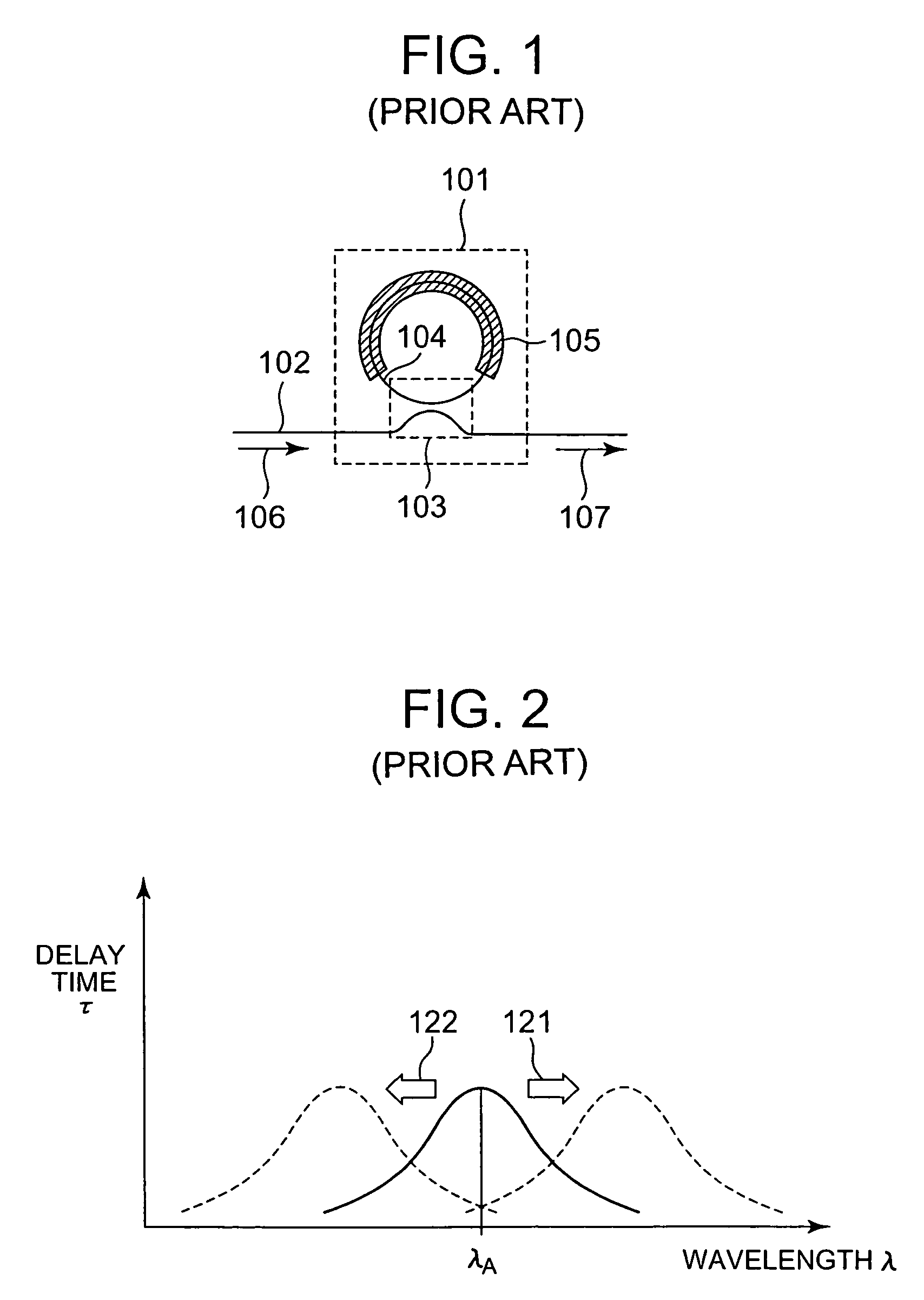
As the transmission rate is increased, a light waveform deteriorates due to chromatic dispersion in an optical fiber.
This causes a problem that the size of the equipment carrying out compensation of chromatic dispersion increases.
Furthermore, since the DCF has quite a large transmission loss of an optical signal, an expensive light amplifier is required to compensate for the transmission loss.
Furthermore, since the DCF has a small core diameter, the optical signal is trapped in a narrow area.
This causes nonlinear interaction, deteriorating the light waveform.
There is another problem that the amount of dispersion compensation cannot be made variable.
Thus, the use of the DCF involves many problems.
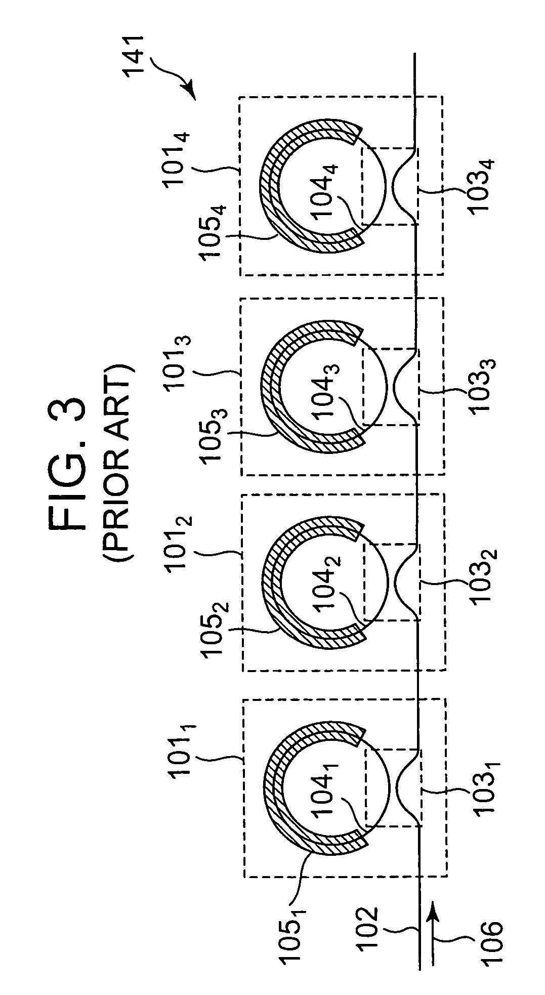
Because of this influence, the S / N ratio (signal to noise ratio) of a main signal deteriorates, making it difficult to accurately determine central wavelengths of the respective ring resonators.
As a result, it is difficult to correct chromatic dispersion of the optical fiber optimally.

Method used


Image

  • Tunable dispersion compensator and method for tunable dispersion compensation
  • Tunable dispersion compensator and method for tunable dispersion compensation
  • Tunable dispersion compensator and method for tunable dispersion compensation

Examples


first embodiment

[0044]Then, the basic structure of a tunable dispersion compensator according to the present invention to solve the above described problems will be explained.

[0045]FIG. 6 shows a schematic structure of the tunable dispersion compensator according to the first embodiment of the present invention provided with four stages of ring resonators. This tunable dispersion compensator 201 connects a total of four stages of first to fourth ring resonators 2021 to 2024 in series along one common linear waveguide 203. The one linear waveguide 203 is provided with first to fifth mold filters 2041 to 2045 in such as way as to sandwich each of the ring resonators 2021 to 2024 from the input side and output side. These mold filters 2041 to 2045 are intended to remove noise components of higher modes which transmit through the linear waveguide 203.

[0046]The first ring resonator 2021 is provided with the linear waveguide 203 which transmits an optical signal 208 output from the first mode filter 2041...

second embodiment

[0059]Then, the basic structure of a tunable dispersion compensator according to the present invention will be explained.

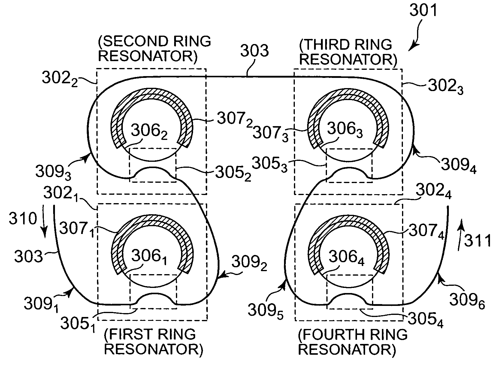
[0060]FIG. 8 shows a schematic structure of the tunable dispersion compensator according to the second embodiment of the present invention. This tunable dispersion compensator 301 is constructed of first to fourth ring resonators 3021 to 3024 connected in series along a common linear waveguide 303. Here, a four-stage structure is shown as an example. The first ring resonator 3021 is constructed of a linear waveguide 303 which, transmits an optical signal, an optical coupler 3051 which distributes the optical signal and a ring-shaped waveguide 3061 which delays the distributed optical signal. The first ring-shaped waveguide 3061 is provided with a heater 3071 for heating and controlling. This heater 3071 is preferably disposed over almost the whole area of the first ring-shaped waveguide 3061 except the area making up the optical coupler 3051. This can make the tem...


PUM


Abstract

A tunable dispersion compensator and a tunable dispersion compensation method having an excellent dispersion compensation characteristic are provided. A tunable dispersion compensator 201 is constructed of first to fourth ring resonators 2021 to 2024 connected in series along a common linear waveguide 203. The linear waveguide 203 is provided with first to fifth mode filters 2041 to 2045 in such a way as to sandwich the ring resonators 2021 to 2024 respectively. These mode filters 2041 to 2045 eliminate high-order mode noise components which transmit through the linear waveguide 203. The mode filters 2041 to 2045 are constructed with the width of a central waveguide reduced or in a curved shape.

Description

BACKGROUND OF THE INVENTION[0001]1. Field of the Invention[0002]The present invention relates to a tunable dispersion compensator and a method for tunable dispersion compensation for compensating dispersion of an optical signal.[0003]2. Description of the Related Art[0004]With the growing demand for information communication, there is a demand for greater transmission capacities. To meet this demand, efforts are being made to increase a transmission rate in an optical communication system. As the transmission rate is increased, a light waveform deteriorates due to chromatic dispersion in an optical fiber. The chromatic dispersion refers to a phenomenon that the rate at which an optical signal propagates through the optical fiber varies depending on the wavelength. Thus, a dispersion compensating fiber (DCF) is widely used to suppress the deterioration of the light waveform due to chromatic dispersion.[0005]The DCF is designed to have a core diameter smaller than that of an ordinary ...

Claims


Application Information

Patent Timeline
Patent Type & Authority Patents(United States)
IPC IPC(8): G02B6/26G02B6/34H04B10/18
CPCG02B6/12007H04B10/25133G02B6/14G02B6/29395G02B6/29398G02B6/29394
Inventor YAMAZAKI, HIROYUKI
Owner NEC CORP
Why Eureka
Try Eureka