Method for producing an aspherical optical element

a technology of optical elements and aspherical lenses, applied in the direction of electrical programme control, program control, instruments, etc., can solve the problems of limited possibilities for modification, correction and movement dynamics, and the grinding results previously achieved with such machines generally did not meet the requirements, and the production of effective series production of highly accurate aspheres, in particular aspherical lenses, is rarely possible or not possible at all, so as to improve the accuracy of asphere grinding results and achieve high accuracy. , the effect o

Active Publication Date: 2007-01-16
CARL ZEISS SMT GMBH
View PDF11 Cites 24 Cited by
  • Summary
  • Abstract
  • Description
  • Claims
  • Application Information

AI Technical Summary

Benefits of technology

[0011]The present invention is therefore based on the object of providing a program-controlled PC data generating method of the type mentioned at the beginning by which the disadvantages of the prior art are overcome; in particular, an improvement in the accuracy of the asphere grinding results is to be achieved, in order to permit effective series production of highly accurate optical aspheres, it being intended to avoid or correct central depressions and steep asphere runout regions.

Problems solved by technology

Although known optical grinding machines allow possibilities for the input of aspherical forms, they offer only very limited possibilities for modification, correction and movement dynamics.
Grinding results previously achieved with such machines generally did not satisfy the requirements that exact aspherical forms have to meet.
Owing to dimensional deviations of up to 10 μm and inadequate correction possibilities, frequently only by means of a few interpolation points, often to be input manually, effective series production of highly accurate aspheres, in particular aspherical lenses, is rarely possible or not possible at all.
The so-called depression in the center of the workpiece is particularly problematical.
The grinding tool or the grinding wheel of a CNC grinding machine, in particular a CNC wet-grinding machine, cannot move away from the center of the asphere infinitely quickly, it is limited in its dynamics.
Even an extremely short dwell time of the grinding wheel in the center (even in the range of milliseconds) can cause a hole or a depression at the center of the lens.
This on the one hand increases the deformation and, since the grinding / polishing tool also adapts itself to the deformations in a disadvantageous way, is accompanied by great problems, which can have effects extending into the useful region of the asphere.
In addition, in the case of concave forms, the useful surface area may be ground into, i.e. destroyed, by the grinding tool.

Method used


Image

  • Method for producing an aspherical optical element
  • Method for producing an aspherical optical element
  • Method for producing an aspherical optical element

Examples


Embodiment Construction

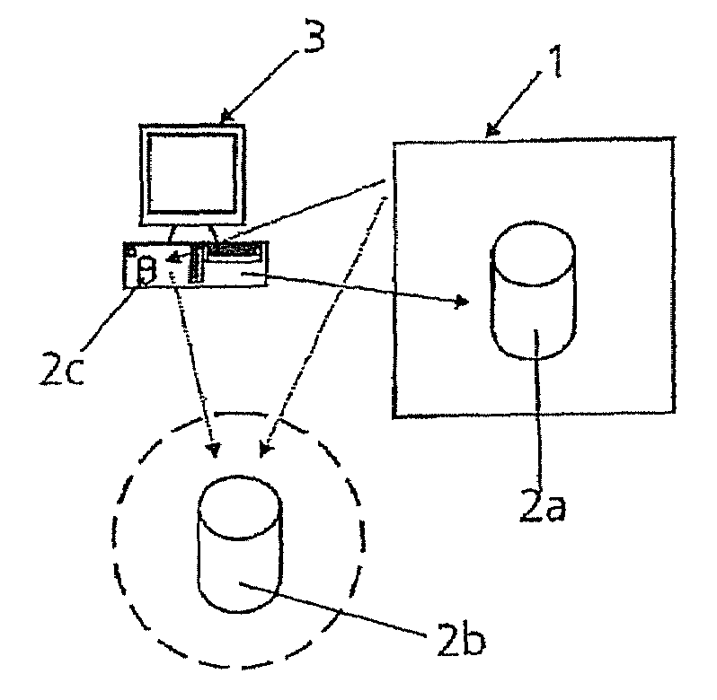
[0032]As represented in FIG. 1, a CNC wet-grinding machine 1 accesses NC data 2a, 2b, 2c (dotted arrows) in order to machine a workpiece; in the present exemplary embodiment it is intended to produce a lens with an aspherical form, in particular for use in projection lenses for microlithography for the production of semiconductor elements. The CNC wet-grinding machine 1 may receive the necessary NC data 2a from storage media of its own or by direct programming. Furthermore, the CNC grinding machine 1 could also obtain the NC data 2b in particular via a network (for example intranet, LAN or the like—indicated in FIG. 1 by dashed line) or via an RS232 interface from a server (not represented) or directly access the database 2c of a computer system 3. In the present exemplary embodiment, a computer program which implements the NC data generating method according to the invention runs on the computer system 3. In this case, NC data 2a, 2b, 2c for the production of an aspherical form are...


PUM


Abstract

The invention relates to a program-controlled NC data generating method for controlling a CNC wet-grinding machine for machining workpieces made of optical materials to produce aspherical forms, the data of the aspherical forms to be ground being overlaid with correction data.

Description

CROSS REFERENCE TO RELATED APPLICATIONS[0001]This is a continuation-in-part of International Application No. PCT / EP04 / 01193 filed Feb. 10, 2004 which designated the U.S. and to which priority is claimed under 35 U.S.C. § 120.STATEMENT REGARDING FEDERALLY SPONSORED RESEARCH OR DEVELOPMENT[0002]Not applicable.THE NAMES OF PARTIES TO A JOINT RESEARCH AGREEMENT[0003]Not applicable.INCORPORATION BY REFERENCE OF MATERIAL SUBMITTED ON A COMPACT DISC[0004]Not applicable.BACKGROUND OF THE INVENTION[0005]1. Field of the Invention[0006]The invention relates to a program-controlled NC data generating method for controlling a CNC wet-grinding machine.[0007]2. Description of Related Art[0008]Although known optical grinding machines allow possibilities for the input of aspherical forms, they offer only very limited possibilities for modification, correction and movement dynamics. Grinding results previously achieved with such machines generally did not satisfy the requirements that exact aspherica...

Claims


Application Information

Patent Timeline
Patent Type & Authority Patents(United States)
IPC IPC(8): G06F19/00B24B13/06G05B19/18G05B19/404
CPCB24B13/06B29D11/00019G05B19/404G05B2219/45157G05B2219/36251G05B2219/37576G05B19/401
Inventor STACKLIES, SIEGFRIED
Owner CARL ZEISS SMT GMBH
Why Eureka
Try Eureka